

382
11 Landing Gear Technology of Lunar Lander
W =
1
2
m max v
2
V + m max g
H
(11.8)
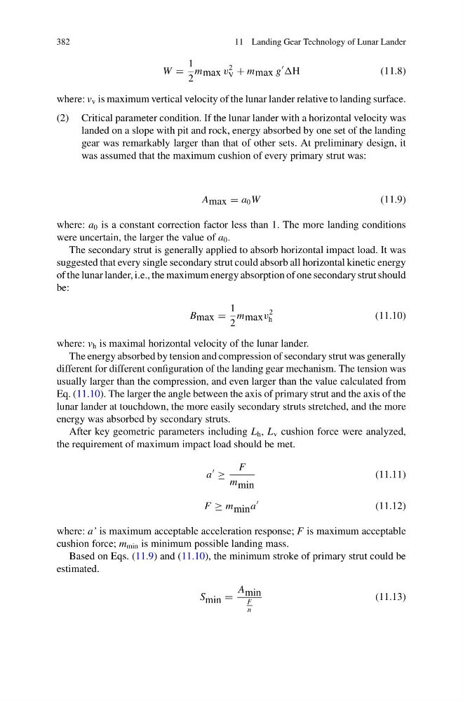
where: v v is maximum vertical velocity of the lunar lander relative to landing surface.
(2) Critical parameter condition. If the lunar lander with a horizontal velocity was
landed on a slope with pit and rock, energy absorbed by one set of the landing
gear was remarkably larger than that of other sets. At preliminary design, it
was assumed that the maximum cushion of every primary strut was:
A max = a 0 W
(11.9)
where: a 0 is a constant correction factor less than 1. The more landing conditions
were uncertain, the larger the value of a 0 .
The secondary strut is generally applied to absorb horizontal impact load. It was
suggested that every single secondary strut could absorb all horizontal kinetic energy
of the lunar lander, i.e., the maximum energy absorption of one secondary strut should
be:
B max =
1
2
m max v
2
h
(11.10)
where: v h is maximal horizontal velocity of the lunar lander.
The energy absorbed by tension and compression of secondary strut was generally
different for different configuration of the landing gear mechanism. The tension was
usually larger than the compression, and even larger than the value calculated from
Eq. (11.10). The larger the angle between the axis of primary strut and the axis of the
lunar lander at touchdown, the more easily secondary struts stretched, and the more
energy was absorbed by secondary struts.
After key geometric parameters including L h , L v cushion force were analyzed,
the requirement of maximum impact load should be met.
a
≥
F
m min
(11.11)
F ≥ m min a
(11.12)
where: a’ is maximum acceptable acceleration response; F is maximum acceptable
cushion force; m min is minimum possible landing mass.
Based on Eqs. (11.9) and (11.10), the minimum stroke of primary strut could be
estimated.
S min =
A min
F
n
(11.13)
11 Landing Gear Technology of Lunar Lander
W =
1
2
m max v
2
V + m max g
H
(11.8)
where: v v is maximum vertical velocity of the lunar lander relative to landing surface.
(2) Critical parameter condition. If the lunar lander with a horizontal velocity was
landed on a slope with pit and rock, energy absorbed by one set of the landing
gear was remarkably larger than that of other sets. At preliminary design, it
was assumed that the maximum cushion of every primary strut was:
A max = a 0 W
(11.9)
where: a 0 is a constant correction factor less than 1. The more landing conditions
were uncertain, the larger the value of a 0 .
The secondary strut is generally applied to absorb horizontal impact load. It was
suggested that every single secondary strut could absorb all horizontal kinetic energy
of the lunar lander, i.e., the maximum energy absorption of one secondary strut should
be:
B max =
1
2
m max v
2
h
(11.10)
where: v h is maximal horizontal velocity of the lunar lander.
The energy absorbed by tension and compression of secondary strut was generally
different for different configuration of the landing gear mechanism. The tension was
usually larger than the compression, and even larger than the value calculated from
Eq. (11.10). The larger the angle between the axis of primary strut and the axis of the
lunar lander at touchdown, the more easily secondary struts stretched, and the more
energy was absorbed by secondary struts.
After key geometric parameters including L h , L v cushion force were analyzed,
the requirement of maximum impact load should be met.
a
≥
F
m min
(11.11)
F ≥ m min a
(11.12)
where: a’ is maximum acceptable acceleration response; F is maximum acceptable
cushion force; m min is minimum possible landing mass.
Based on Eqs. (11.9) and (11.10), the minimum stroke of primary strut could be
estimated.
S min =
A min
F
n
(11.13)