

11.5 Design of Landing Gear Mechanism
379
11.5.2 Design and Simulation
1. Configuration and Cushion Parameters
1) Analysis of layout and configuration
(1) Layout. Generally, there were several uniformly distributed sets of landing
gear mechanisms installed on the bottom and lateral plates. The attachment points of struts and structure should have enough stiffness and
strength due to huge concentrated load of landing impact. Therefore, integrated layout design should be conducted for landing gear mechanisms
and main structure of the lunar lander.
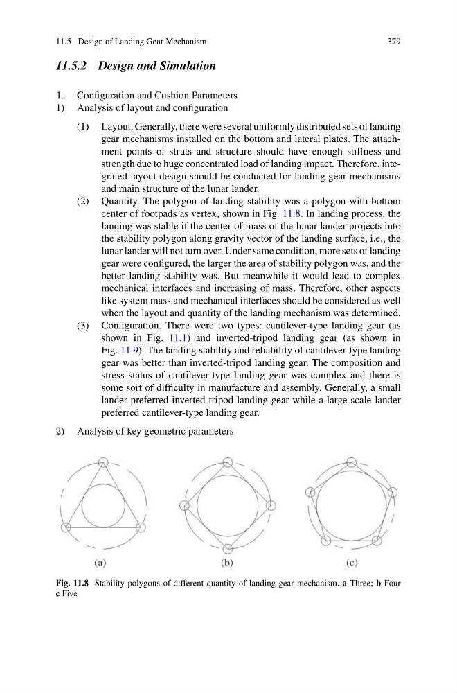
(2) Quantity. The polygon of landing stability was a polygon with bottom
center of footpads as vertex, shown in Fig. 11.8. In landing process, the
landing was stable if the center of mass of the lunar lander projects into
the stability polygon along gravity vector of the landing surface, i.e., the
lunar lander will not turn over. Under same condition, more sets of landing
gear were configured, the larger the area of stability polygon was, and the
better landing stability was. But meanwhile it would lead to complex
mechanical interfaces and increasing of mass. Therefore, other aspects
like system mass and mechanical interfaces should be considered as well
when the layout and quantity of the landing mechanism was determined.
(3) Configuration. There were two types: cantilever-type landing gear (as
shown in Fig. 11.1) and inverted-tripod landing gear (as shown in
Fig. 11.9). The landing stability and reliability of cantilever-type landing
gear was better than inverted-tripod landing gear. The composition and
stress status of cantilever-type landing gear was complex and there is
some sort of difficulty in manufacture and assembly. Generally, a small
lander preferred inverted-tripod landing gear while a large-scale lander
preferred cantilever-type landing gear.
2) Analysis of key geometric parameters
Fig. 11.8 Stability polygons of different quantity of landing gear mechanism. a Three; b Four
c Five
379
11.5.2 Design and Simulation
1. Configuration and Cushion Parameters
1) Analysis of layout and configuration
(1) Layout. Generally, there were several uniformly distributed sets of landing
gear mechanisms installed on the bottom and lateral plates. The attachment points of struts and structure should have enough stiffness and
strength due to huge concentrated load of landing impact. Therefore, integrated layout design should be conducted for landing gear mechanisms
and main structure of the lunar lander.
(2) Quantity. The polygon of landing stability was a polygon with bottom
center of footpads as vertex, shown in Fig. 11.8. In landing process, the
landing was stable if the center of mass of the lunar lander projects into
the stability polygon along gravity vector of the landing surface, i.e., the
lunar lander will not turn over. Under same condition, more sets of landing
gear were configured, the larger the area of stability polygon was, and the
better landing stability was. But meanwhile it would lead to complex
mechanical interfaces and increasing of mass. Therefore, other aspects
like system mass and mechanical interfaces should be considered as well
when the layout and quantity of the landing mechanism was determined.
(3) Configuration. There were two types: cantilever-type landing gear (as
shown in Fig. 11.1) and inverted-tripod landing gear (as shown in
Fig. 11.9). The landing stability and reliability of cantilever-type landing
gear was better than inverted-tripod landing gear. The composition and
stress status of cantilever-type landing gear was complex and there is
some sort of difficulty in manufacture and assembly. Generally, a small
lander preferred inverted-tripod landing gear while a large-scale lander
preferred cantilever-type landing gear.
2) Analysis of key geometric parameters
Fig. 11.8 Stability polygons of different quantity of landing gear mechanism. a Three; b Four
c Five