

374
11 Landing Gear Technology of Lunar Lander
3. Lubrication\between expanding tubes and conical cylinder is the key to
consistency of cushioning features.
Such method was applied used in seat cushion mechanism for astronaut of ShenZhou
spacecraft.
11.4.3 Hydraulic Damping
The hydraulic buffer absorbs impact energy by hydraulic damping force. When the
external force acts on the buffer, hydraulic fluid flows through the orifice resulting
in pressure difference between two sides of the valve, so as to generate damping
force to absorb impact energy. Generally, the hydraulic buffer takes both fluid and
gas as the medium. Because the mass density, pressure, coefficient of viscosity of the
fluid and gas is closely related to temperature, it is necessary to decrease influence of
temperature over these parameters as much as possible to achieve stable cushioning
performance. Furthermore, sealing of fluid and gas medium has to be solved under
temperature alternation. It is a great challenge to design the hydraulic buffer with
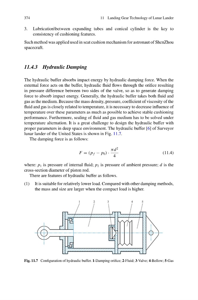
proper parameters in deep space environment. The hydraulic buffer [6] of Surveyor
lunar lander of the United States is shown in Fig. 11.7.
The damping force is as follows:
F = ( p f − p 0 ) ·
π d
2
4
(11.4)
where: p 1 is pressure of internal fluid; p 2 is pressure of ambient pressure; d is the
cross-section diameter of piston rod.
There are features of hydraulic buffer as follows.
(1) It is suitable for relatively lower load. Compared with other damping methods,
the mass and size are larger when the compact load is higher.
Fig. 11.7 Configuration of hydraulic buffer. 1-Damping orifice; 2-Fluid; 3-Valve; 4-Bellow; 5-Gas
11 Landing Gear Technology of Lunar Lander
3. Lubrication\between expanding tubes and conical cylinder is the key to
consistency of cushioning features.
Such method was applied used in seat cushion mechanism for astronaut of ShenZhou
spacecraft.
11.4.3 Hydraulic Damping
The hydraulic buffer absorbs impact energy by hydraulic damping force. When the
external force acts on the buffer, hydraulic fluid flows through the orifice resulting
in pressure difference between two sides of the valve, so as to generate damping
force to absorb impact energy. Generally, the hydraulic buffer takes both fluid and
gas as the medium. Because the mass density, pressure, coefficient of viscosity of the
fluid and gas is closely related to temperature, it is necessary to decrease influence of
temperature over these parameters as much as possible to achieve stable cushioning
performance. Furthermore, sealing of fluid and gas medium has to be solved under
temperature alternation. It is a great challenge to design the hydraulic buffer with
proper parameters in deep space environment. The hydraulic buffer [6] of Surveyor
lunar lander of the United States is shown in Fig. 11.7.
The damping force is as follows:
F = ( p f − p 0 ) ·
π d
2
4
(11.4)
where: p 1 is pressure of internal fluid; p 2 is pressure of ambient pressure; d is the
cross-section diameter of piston rod.
There are features of hydraulic buffer as follows.
(1) It is suitable for relatively lower load. Compared with other damping methods,
the mass and size are larger when the compact load is higher.
Fig. 11.7 Configuration of hydraulic buffer. 1-Damping orifice; 2-Fluid; 3-Valve; 4-Bellow; 5-Gas