

362
10 TT&C and Telecommunication Technology …
Transmitter of
Bit Error Tester
UHF transmitter
Receiver of
Bit Error Tester
UHF receiver
Controller and test
instrument of UHF
receiver
UHF
transmitting
antenna
UHF receiving
antenna
Spectrum
Analyzer
Splitter
Controller and test
instrument of UHF
transmitter
Attenuator
Power
supply
instrument
Power
supply
instrument
Fig. 10.15 Block diagram of ground test system for telecommunication on lunar surface
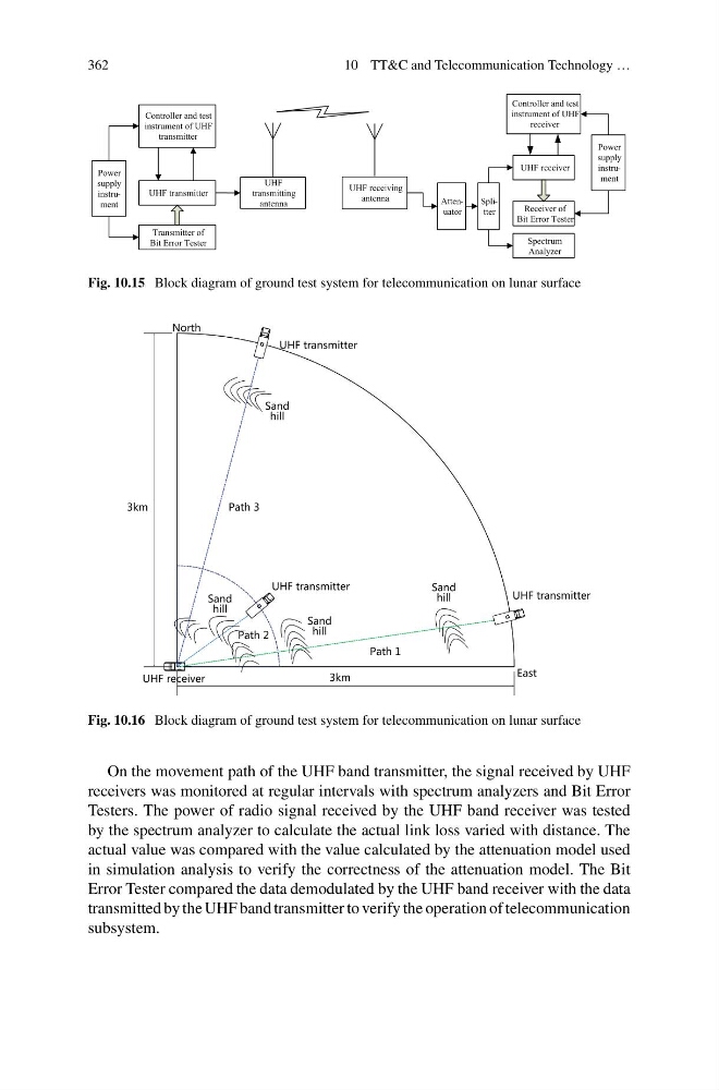
Fig. 10.16 Block diagram of ground test system for telecommunication on lunar surface
On the movement path of the UHF band transmitter, the signal received by UHF
receivers was monitored at regular intervals with spectrum analyzers and Bit Error
Testers. The power of radio signal received by the UHF band receiver was tested
by the spectrum analyzer to calculate the actual link loss varied with distance. The
actual value was compared with the value calculated by the attenuation model used
in simulation analysis to verify the correctness of the attenuation model. The Bit
Error Tester compared the data demodulated by the UHF band receiver with the data
transmitted by the UHF band transmitter to verify the operation of telecommunication
subsystem.
10 TT&C and Telecommunication Technology …
Transmitter of
Bit Error Tester
UHF transmitter
Receiver of
Bit Error Tester
UHF receiver
Controller and test
instrument of UHF
receiver
UHF
transmitting
antenna
UHF receiving
antenna
Spectrum
Analyzer
Splitter
Controller and test
instrument of UHF
transmitter
Attenuator
Power
supply
instrument
Power
supply
instrument
Fig. 10.15 Block diagram of ground test system for telecommunication on lunar surface
Fig. 10.16 Block diagram of ground test system for telecommunication on lunar surface
On the movement path of the UHF band transmitter, the signal received by UHF
receivers was monitored at regular intervals with spectrum analyzers and Bit Error
Testers. The power of radio signal received by the UHF band receiver was tested
by the spectrum analyzer to calculate the actual link loss varied with distance. The
actual value was compared with the value calculated by the attenuation model used
in simulation analysis to verify the correctness of the attenuation model. The Bit
Error Tester compared the data demodulated by the UHF band receiver with the data
transmitted by the UHF band transmitter to verify the operation of telecommunication
subsystem.