

360
10 TT&C and Telecommunication Technology …
was in receiving. The spacecraft antenna to be tested was connected with the receiver
system of compaction field with the test system. The turntable was controlled by
computer software to rotate the spacecraft. The radiation pattern of the antenna
installed on the spacecraft was acquired through related instrument and equipment
for data acquisition and processing.
During the antenna pattern test, the antenna gain of the lunar lander could be
calibrated by means of the comparison method. After processed by software, the
gain coverage map of the antenna coverage area could be obtained. The principle
of the comparison method for calibration of the antenna gain was as follows: In
the same test, the antenna to be tested and the gain standard antenna were tested to
acquire the received power P T of the tested antenna and the received power P S of
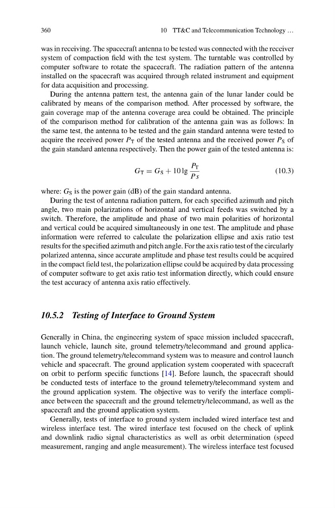
the gain standard antenna respectively. Then the power gain of the tested antenna is:
G T = G S + 10 lg
P T
Ps
(10.3)
where: G S is the power gain (dB) of the gain standard antenna.
During the test of antenna radiation pattern, for each specified azimuth and pitch
angle, two main polarizations of horizontal and vertical feeds was switched by a
switch. Therefore, the amplitude and phase of two main polarities of horizontal
and vertical could be acquired simultaneously in one test. The amplitude and phase
information were referred to calculate the polarization ellipse and axis ratio test
results for the specified azimuth and pitch angle. For the axis ratio test of the circularly
polarized antenna, since accurate amplitude and phase test results could be acquired
in the compact field test, the polarization ellipse could be acquired by data processing
of computer software to get axis ratio test information directly, which could ensure
the test accuracy of antenna axis ratio effectively.
10.5.2 Testing of Interface to Ground System
Generally in China, the engineering system of space mission included spacecraft,
launch vehicle, launch site, ground telemetry/telecommand and ground application. The ground telemetry/telecommand system was to measure and control launch
vehicle and spacecraft. The ground application system cooperated with spacecraft
on orbit to perform specific functions [14]. Before launch, the spacecraft should
be conducted tests of interface to the ground telemetry/telecommand system and
the ground application system. The objective was to verify the interface compliance between the spacecraft and the ground telemetry/telecommand, as well as the
spacecraft and the ground application system.
Generally, tests of interface to ground system included wired interface test and
wireless interface test. The wired interface test focused on the check of uplink
and downlink radio signal characteristics as well as orbit determination (speed
measurement, ranging and angle measurement). The wireless interface test focused
10 TT&C and Telecommunication Technology …
was in receiving. The spacecraft antenna to be tested was connected with the receiver
system of compaction field with the test system. The turntable was controlled by
computer software to rotate the spacecraft. The radiation pattern of the antenna
installed on the spacecraft was acquired through related instrument and equipment
for data acquisition and processing.
During the antenna pattern test, the antenna gain of the lunar lander could be
calibrated by means of the comparison method. After processed by software, the
gain coverage map of the antenna coverage area could be obtained. The principle
of the comparison method for calibration of the antenna gain was as follows: In
the same test, the antenna to be tested and the gain standard antenna were tested to
acquire the received power P T of the tested antenna and the received power P S of
the gain standard antenna respectively. Then the power gain of the tested antenna is:
G T = G S + 10 lg
P T
Ps
(10.3)
where: G S is the power gain (dB) of the gain standard antenna.
During the test of antenna radiation pattern, for each specified azimuth and pitch
angle, two main polarizations of horizontal and vertical feeds was switched by a
switch. Therefore, the amplitude and phase of two main polarities of horizontal
and vertical could be acquired simultaneously in one test. The amplitude and phase
information were referred to calculate the polarization ellipse and axis ratio test
results for the specified azimuth and pitch angle. For the axis ratio test of the circularly
polarized antenna, since accurate amplitude and phase test results could be acquired
in the compact field test, the polarization ellipse could be acquired by data processing
of computer software to get axis ratio test information directly, which could ensure
the test accuracy of antenna axis ratio effectively.
10.5.2 Testing of Interface to Ground System
Generally in China, the engineering system of space mission included spacecraft,
launch vehicle, launch site, ground telemetry/telecommand and ground application. The ground telemetry/telecommand system was to measure and control launch
vehicle and spacecraft. The ground application system cooperated with spacecraft
on orbit to perform specific functions [14]. Before launch, the spacecraft should
be conducted tests of interface to the ground telemetry/telecommand system and
the ground application system. The objective was to verify the interface compliance between the spacecraft and the ground telemetry/telecommand, as well as the
spacecraft and the ground application system.
Generally, tests of interface to ground system included wired interface test and
wireless interface test. The wired interface test focused on the check of uplink
and downlink radio signal characteristics as well as orbit determination (speed
measurement, ranging and angle measurement). The wireless interface test focused