

8.4 Propulsion Subsystem Design [5–7]
289
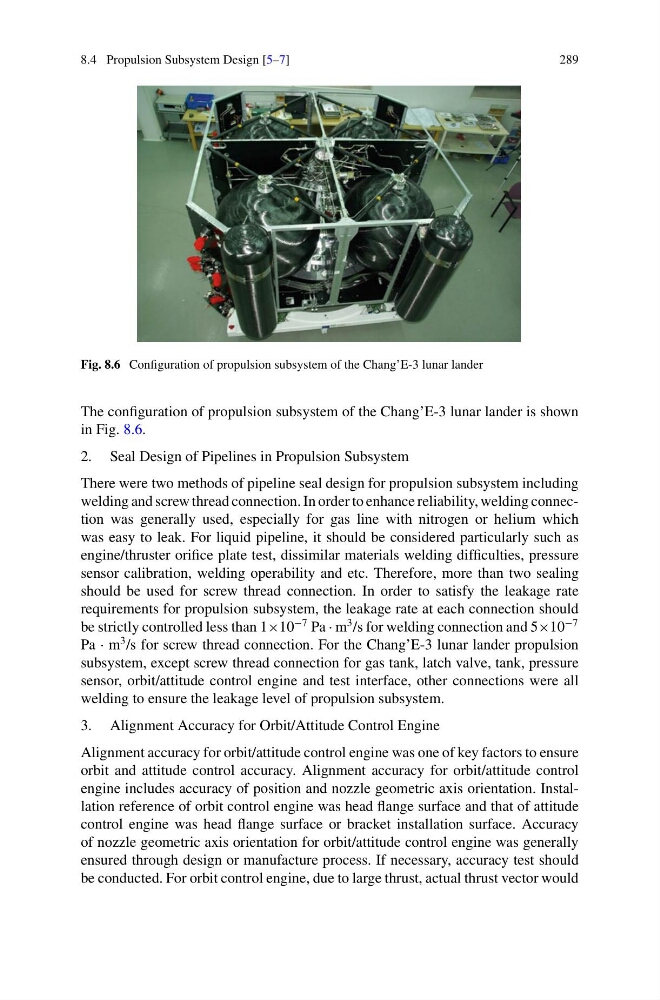
Fig. 8.6 Configuration of propulsion subsystem of the Chang’E-3 lunar lander
The configuration of propulsion subsystem of the Chang’E-3 lunar lander is shown
in Fig. 8.6.
2. Seal Design of Pipelines in Propulsion Subsystem
There were two methods of pipeline seal design for propulsion subsystem including
welding and screw thread connection. In order to enhance reliability, welding connection was generally used, especially for gas line with nitrogen or helium which
was easy to leak. For liquid pipeline, it should be considered particularly such as
engine/thruster orifice plate test, dissimilar materials welding difficulties, pressure
sensor calibration, welding operability and etc. Therefore, more than two sealing
should be used for screw thread connection. In order to satisfy the leakage rate
requirements for propulsion subsystem, the leakage rate at each connection should
be strictly controlled less than 1×10
−7 Pa · m
3 /s for welding connection and 5×10
−7
Pa · m
3 /s for screw thread connection. For the Chang’E-3 lunar lander propulsion
subsystem, except screw thread connection for gas tank, latch valve, tank, pressure
sensor, orbit/attitude control engine and test interface, other connections were all
welding to ensure the leakage level of propulsion subsystem.
3. Alignment Accuracy for Orbit/Attitude Control Engine
Alignment accuracy for orbit/attitude control engine was one of key factors to ensure
orbit and attitude control accuracy. Alignment accuracy for orbit/attitude control
engine includes accuracy of position and nozzle geometric axis orientation. Installation reference of orbit control engine was head flange surface and that of attitude
control engine was head flange surface or bracket installation surface. Accuracy
of nozzle geometric axis orientation for orbit/attitude control engine was generally
ensured through design or manufacture process. If necessary, accuracy test should
be conducted. For orbit control engine, due to large thrust, actual thrust vector would
289
Fig. 8.6 Configuration of propulsion subsystem of the Chang’E-3 lunar lander
The configuration of propulsion subsystem of the Chang’E-3 lunar lander is shown
in Fig. 8.6.
2. Seal Design of Pipelines in Propulsion Subsystem
There were two methods of pipeline seal design for propulsion subsystem including
welding and screw thread connection. In order to enhance reliability, welding connection was generally used, especially for gas line with nitrogen or helium which
was easy to leak. For liquid pipeline, it should be considered particularly such as
engine/thruster orifice plate test, dissimilar materials welding difficulties, pressure
sensor calibration, welding operability and etc. Therefore, more than two sealing
should be used for screw thread connection. In order to satisfy the leakage rate
requirements for propulsion subsystem, the leakage rate at each connection should
be strictly controlled less than 1×10
−7 Pa · m
3 /s for welding connection and 5×10
−7
Pa · m
3 /s for screw thread connection. For the Chang’E-3 lunar lander propulsion
subsystem, except screw thread connection for gas tank, latch valve, tank, pressure
sensor, orbit/attitude control engine and test interface, other connections were all
welding to ensure the leakage level of propulsion subsystem.
3. Alignment Accuracy for Orbit/Attitude Control Engine
Alignment accuracy for orbit/attitude control engine was one of key factors to ensure
orbit and attitude control accuracy. Alignment accuracy for orbit/attitude control
engine includes accuracy of position and nozzle geometric axis orientation. Installation reference of orbit control engine was head flange surface and that of attitude
control engine was head flange surface or bracket installation surface. Accuracy
of nozzle geometric axis orientation for orbit/attitude control engine was generally
ensured through design or manufacture process. If necessary, accuracy test should
be conducted. For orbit control engine, due to large thrust, actual thrust vector would