

8.4 Propulsion Subsystem Design [5–7]
287
same function and numbers. Since the orbit control engine was fired only few times
and shut off during long term orbital flight, the propellant feed could be cut off by
shutting down upstream latch valve to avoid permanent propellant leak because of
leak failure of the orbit engine. When an attitude control thruster could not be fired, it
could be switched to the corresponding attitude control thruster on the other feed line.
When there was leak failure in one branch of attitude control thrusters, the whole
branch could be switched off by shutting down upstream latch valve on a certain
feed line. In order to monitor liquid pipelines and operation status of orbit/attitude
control engines, there were pressure sensors on inlet pipelines of orbit control engine
and attitude control thruster on A/B two branches, and temperature sensors on liquid
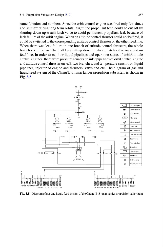
pipelines, injector of engine and thrusters, valve and etc. The diagram of gas and
liquid feed system of the Chang’E-3 lunar lander propulsion subsystem is shown in
Fig. 8.5.
CS5
CS6
Diaphragm valve
2
1
P10
P
P11
P
P9
P
P12
P
LV
LV
LV
LV
LV
LV5
LV
LV2
LV
P7
P8
P5
P6
P4
P3
P2
P1
P
7500N
CS4
CS3
LV
LV9
LV
LV
P
Latch valve
2
2
1
1
CS2
P
He
P
P
P
P
7500NEngine
He
Gas tank
Oxidizer tank
10 Thruster
15 Thruster
P
Pressure sensor
Pyro valve
Gas fill valve
Fuel tank
Fill valve
Regulator
Safety valve
Test interface
RV
P PV2
He
SV
P
CS1
PV1
P
P
P
PV3
Fig. 8.5 Diagram of gas and liquid feed system of the Chang’E-3 lunar lander propulsion subsystem
287
same function and numbers. Since the orbit control engine was fired only few times
and shut off during long term orbital flight, the propellant feed could be cut off by
shutting down upstream latch valve to avoid permanent propellant leak because of
leak failure of the orbit engine. When an attitude control thruster could not be fired, it
could be switched to the corresponding attitude control thruster on the other feed line.
When there was leak failure in one branch of attitude control thrusters, the whole
branch could be switched off by shutting down upstream latch valve on a certain
feed line. In order to monitor liquid pipelines and operation status of orbit/attitude
control engines, there were pressure sensors on inlet pipelines of orbit control engine
and attitude control thruster on A/B two branches, and temperature sensors on liquid
pipelines, injector of engine and thrusters, valve and etc. The diagram of gas and
liquid feed system of the Chang’E-3 lunar lander propulsion subsystem is shown in
Fig. 8.5.
CS5
CS6
Diaphragm valve
2
1
P10
P
P11
P
P9
P
P12
P
LV
LV
LV
LV
LV
LV5
LV
LV2
LV
P7
P8
P5
P6
P4
P3
P2
P1
P
7500N
CS4
CS3
LV
LV9
LV
LV
P
Latch valve
2
2
1
1
CS2
P
He
P
P
P
P
7500NEngine
He
Gas tank
Oxidizer tank
10 Thruster
15 Thruster
P
Pressure sensor
Pyro valve
Gas fill valve
Fuel tank
Fill valve
Regulator
Safety valve
Test interface
RV
P PV2
He
SV
P
CS1
PV1
P
P
P
PV3
Fig. 8.5 Diagram of gas and liquid feed system of the Chang’E-3 lunar lander propulsion subsystem