

7.6 Testing and Verification
259
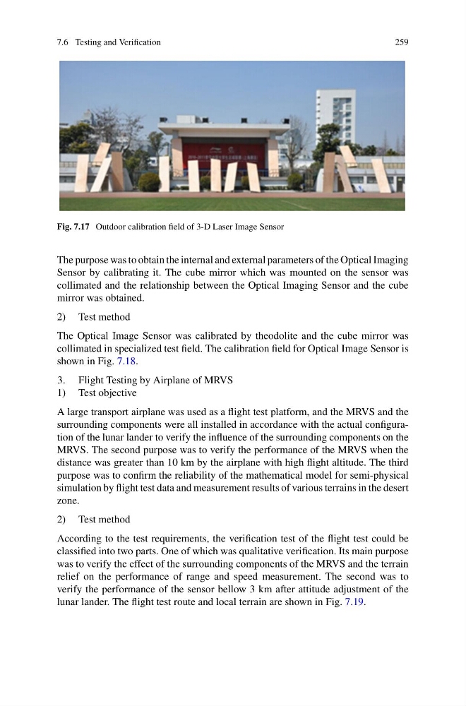
Fig. 7.17 Outdoor calibration field of 3-D Laser Image Sensor
The purpose was to obtain the internal and external parameters of the Optical Imaging
Sensor by calibrating it. The cube mirror which was mounted on the sensor was
collimated and the relationship between the Optical Imaging Sensor and the cube
mirror was obtained.
2) Test method
The Optical Image Sensor was calibrated by theodolite and the cube mirror was
collimated in specialized test field. The calibration field for Optical Image Sensor is
shown in Fig. 7.18.
3. Flight Testing by Airplane of MRVS
1) Test objective
A large transport airplane was used as a flight test platform, and the MRVS and the
surrounding components were all installed in accordance with the actual configuration of the lunar lander to verify the influence of the surrounding components on the
MRVS. The second purpose was to verify the performance of the MRVS when the
distance was greater than 10 km by the airplane with high flight altitude. The third
purpose was to confirm the reliability of the mathematical model for semi-physical
simulation by flight test data and measurement results of various terrains in the desert
zone.
2) Test method
According to the test requirements, the verification test of the flight test could be
classified into two parts. One of which was qualitative verification. Its main purpose
was to verify the effect of the surrounding components of the MRVS and the terrain
relief on the performance of range and speed measurement. The second was to
verify the performance of the sensor bellow 3 km after attitude adjustment of the
lunar lander. The flight test route and local terrain are shown in Fig. 7.19.
259
Fig. 7.17 Outdoor calibration field of 3-D Laser Image Sensor
The purpose was to obtain the internal and external parameters of the Optical Imaging
Sensor by calibrating it. The cube mirror which was mounted on the sensor was
collimated and the relationship between the Optical Imaging Sensor and the cube
mirror was obtained.
2) Test method
The Optical Image Sensor was calibrated by theodolite and the cube mirror was
collimated in specialized test field. The calibration field for Optical Image Sensor is
shown in Fig. 7.18.
3. Flight Testing by Airplane of MRVS
1) Test objective
A large transport airplane was used as a flight test platform, and the MRVS and the
surrounding components were all installed in accordance with the actual configuration of the lunar lander to verify the influence of the surrounding components on the
MRVS. The second purpose was to verify the performance of the MRVS when the
distance was greater than 10 km by the airplane with high flight altitude. The third
purpose was to confirm the reliability of the mathematical model for semi-physical
simulation by flight test data and measurement results of various terrains in the desert
zone.
2) Test method
According to the test requirements, the verification test of the flight test could be
classified into two parts. One of which was qualitative verification. Its main purpose
was to verify the effect of the surrounding components of the MRVS and the terrain
relief on the performance of range and speed measurement. The second was to
verify the performance of the sensor bellow 3 km after attitude adjustment of the
lunar lander. The flight test route and local terrain are shown in Fig. 7.19.