

236
7 Guidance, Navigation and Control Technology …
Optical Image Sensor
Optical System
Mechanical
Structure
Detector Circuits
Software
APS Drive ,
Secondary
Power
DSP
Board
Detector Structure,
Lens Hood, etc
Image Processing,
Image
Transmission
DPU
Video
Amplifier,
A/D, etc
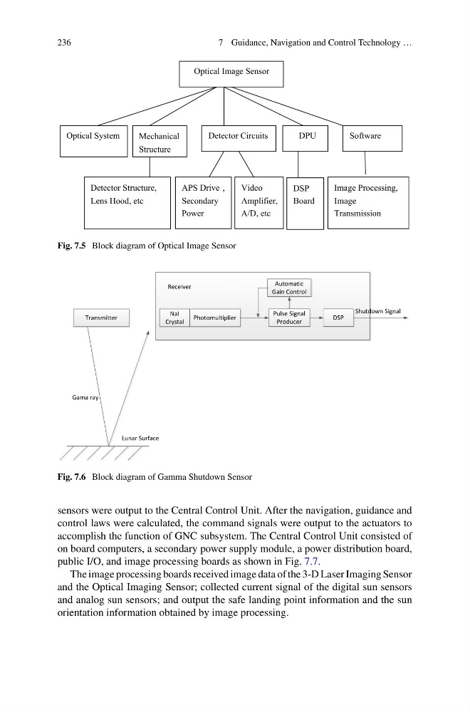
Fig. 7.5 Block diagram of Optical Image Sensor
Gama ray
Transmitter
NaI
Crystal
Photomultiplier
Pulse Signal
Producer
DSP
Automatic
Gain Control
Lunar Surface
Receiver
Shutdown Signal
Fig. 7.6 Block diagram of Gamma Shutdown Sensor
sensors were output to the Central Control Unit. After the navigation, guidance and
control laws were calculated, the command signals were output to the actuators to
accomplish the function of GNC subsystem. The Central Control Unit consisted of
on board computers, a secondary power supply module, a power distribution board,
public I/O, and image processing boards as shown in Fig. 7.7.
The image processing boards received image data of the 3-D Laser Imaging Sensor
and the Optical Imaging Sensor; collected current signal of the digital sun sensors
and analog sun sensors; and output the safe landing point information and the sun
orientation information obtained by image processing.
7 Guidance, Navigation and Control Technology …
Optical Image Sensor
Optical System
Mechanical
Structure
Detector Circuits
Software
APS Drive ,
Secondary
Power
DSP
Board
Detector Structure,
Lens Hood, etc
Image Processing,
Image
Transmission
DPU
Video
Amplifier,
A/D, etc
Fig. 7.5 Block diagram of Optical Image Sensor
Gama ray
Transmitter
NaI
Crystal
Photomultiplier
Pulse Signal
Producer
DSP
Automatic
Gain Control
Lunar Surface
Receiver
Shutdown Signal
Fig. 7.6 Block diagram of Gamma Shutdown Sensor
sensors were output to the Central Control Unit. After the navigation, guidance and
control laws were calculated, the command signals were output to the actuators to
accomplish the function of GNC subsystem. The Central Control Unit consisted of
on board computers, a secondary power supply module, a power distribution board,
public I/O, and image processing boards as shown in Fig. 7.7.
The image processing boards received image data of the 3-D Laser Imaging Sensor
and the Optical Imaging Sensor; collected current signal of the digital sun sensors
and analog sun sensors; and output the safe landing point information and the sun
orientation information obtained by image processing.