

234
7 Guidance, Navigation and Control Technology …
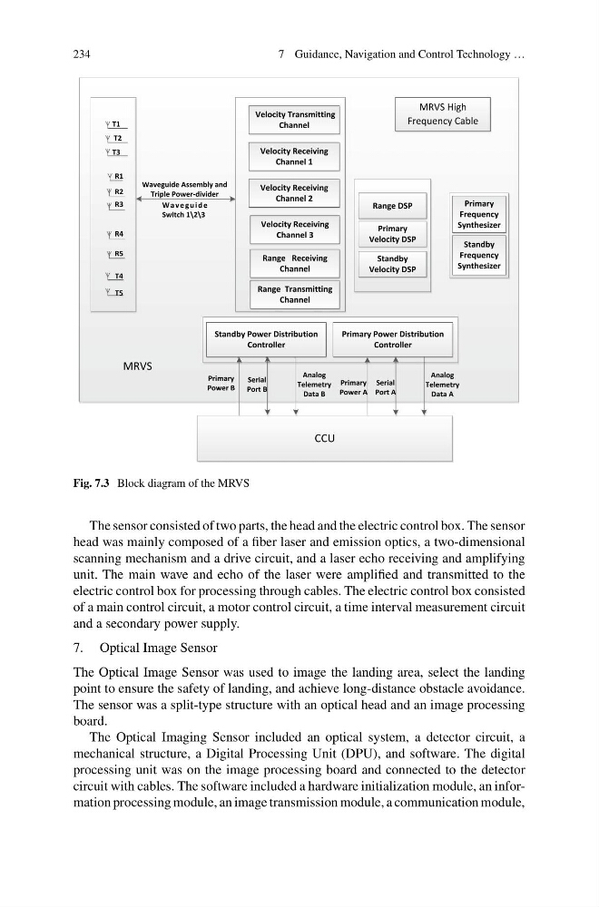
Fig. 7.3 Block diagram of the MRVS
The sensor consisted of two parts, the head and the electric control box. The sensor
head was mainly composed of a fiber laser and emission optics, a two-dimensional
scanning mechanism and a drive circuit, and a laser echo receiving and amplifying
unit. The main wave and echo of the laser were amplified and transmitted to the
electric control box for processing through cables. The electric control box consisted
of a main control circuit, a motor control circuit, a time interval measurement circuit
and a secondary power supply.
7. Optical Image Sensor
The Optical Image Sensor was used to image the landing area, select the landing
point to ensure the safety of landing, and achieve long-distance obstacle avoidance.
The sensor was a split-type structure with an optical head and an image processing
board.
The Optical Imaging Sensor included an optical system, a detector circuit, a
mechanical structure, a Digital Processing Unit (DPU), and software. The digital
processing unit was on the image processing board and connected to the detector
circuit with cables. The software included a hardware initialization module, an information processing module, an image transmission module, a communication module,
7 Guidance, Navigation and Control Technology …
Fig. 7.3 Block diagram of the MRVS
The sensor consisted of two parts, the head and the electric control box. The sensor
head was mainly composed of a fiber laser and emission optics, a two-dimensional
scanning mechanism and a drive circuit, and a laser echo receiving and amplifying
unit. The main wave and echo of the laser were amplified and transmitted to the
electric control box for processing through cables. The electric control box consisted
of a main control circuit, a motor control circuit, a time interval measurement circuit
and a secondary power supply.
7. Optical Image Sensor
The Optical Image Sensor was used to image the landing area, select the landing
point to ensure the safety of landing, and achieve long-distance obstacle avoidance.
The sensor was a split-type structure with an optical head and an image processing
board.
The Optical Imaging Sensor included an optical system, a detector circuit, a
mechanical structure, a Digital Processing Unit (DPU), and software. The digital
processing unit was on the image processing board and connected to the detector
circuit with cables. The software included a hardware initialization module, an information processing module, an image transmission module, a communication module,