

232
7 Guidance, Navigation and Control Technology …
Central Control Unit
Primary Image Process Board
DSS1
DSS2
ASS1
ASS2
Standby Image Process Board
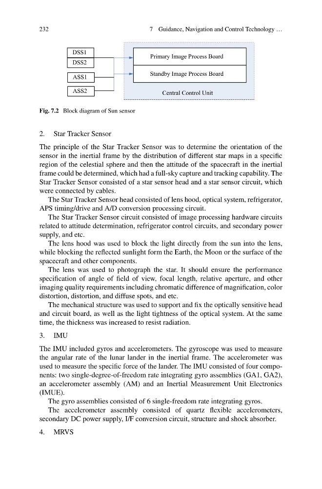
Fig. 7.2 Block diagram of Sun sensor
2. Star Tracker Sensor
The principle of the Star Tracker Sensor was to determine the orientation of the
sensor in the inertial frame by the distribution of different star maps in a specific
region of the celestial sphere and then the attitude of the spacecraft in the inertial
frame could be determined, which had a full-sky capture and tracking capability. The
Star Tracker Sensor consisted of a star sensor head and a star sensor circuit, which
were connected by cables.
The Star Tracker Sensor head consisted of lens hood, optical system, refrigerator,
APS timing/drive and A/D conversion processing circuit.
The Star Tracker Sensor circuit consisted of image processing hardware circuits
related to attitude determination, refrigerator control circuits, and secondary power
supply, and etc.
The lens hood was used to block the light directly from the sun into the lens,
while blocking the reflected sunlight form the Earth, the Moon or the surface of the
spacecraft and other components.
The lens was used to photograph the star. It should ensure the performance
specification of angle of field of view, focal length, relative aperture, and other
imaging quality requirements including chromatic difference of magnification, color
distortion, distortion, and diffuse spots, and etc.
The mechanical structure was used to support and fix the optically sensitive head
and circuit board, as well as the light tightness of the optical system. At the same
time, the thickness was increased to resist radiation.
3. IMU
The IMU included gyros and accelerometers. The gyroscope was used to measure
the angular rate of the lunar lander in the inertial frame. The accelerometer was
used to measure the specific force of the lander. The IMU consisted of four components: two single-degree-of-freedom rate integrating gyro assemblies (GA1, GA2),
an accelerometer assembly (AM) and an Inertial Measurement Unit Electronics
(IMUE).
The gyro assemblies consisted of 6 single-freedom rate integrating gyros.
The accelerometer assembly consisted of quartz flexible accelerometers,
secondary DC power supply, I/F conversion circuit, structure and shock absorber.
4. MRVS
7 Guidance, Navigation and Control Technology …
Central Control Unit
Primary Image Process Board
DSS1
DSS2
ASS1
ASS2
Standby Image Process Board
Fig. 7.2 Block diagram of Sun sensor
2. Star Tracker Sensor
The principle of the Star Tracker Sensor was to determine the orientation of the
sensor in the inertial frame by the distribution of different star maps in a specific
region of the celestial sphere and then the attitude of the spacecraft in the inertial
frame could be determined, which had a full-sky capture and tracking capability. The
Star Tracker Sensor consisted of a star sensor head and a star sensor circuit, which
were connected by cables.
The Star Tracker Sensor head consisted of lens hood, optical system, refrigerator,
APS timing/drive and A/D conversion processing circuit.
The Star Tracker Sensor circuit consisted of image processing hardware circuits
related to attitude determination, refrigerator control circuits, and secondary power
supply, and etc.
The lens hood was used to block the light directly from the sun into the lens,
while blocking the reflected sunlight form the Earth, the Moon or the surface of the
spacecraft and other components.
The lens was used to photograph the star. It should ensure the performance
specification of angle of field of view, focal length, relative aperture, and other
imaging quality requirements including chromatic difference of magnification, color
distortion, distortion, and diffuse spots, and etc.
The mechanical structure was used to support and fix the optically sensitive head
and circuit board, as well as the light tightness of the optical system. At the same
time, the thickness was increased to resist radiation.
3. IMU
The IMU included gyros and accelerometers. The gyroscope was used to measure
the angular rate of the lunar lander in the inertial frame. The accelerometer was
used to measure the specific force of the lander. The IMU consisted of four components: two single-degree-of-freedom rate integrating gyro assemblies (GA1, GA2),
an accelerometer assembly (AM) and an Inertial Measurement Unit Electronics
(IMUE).
The gyro assemblies consisted of 6 single-freedom rate integrating gyros.
The accelerometer assembly consisted of quartz flexible accelerometers,
secondary DC power supply, I/F conversion circuit, structure and shock absorber.
4. MRVS