

226
7 Guidance, Navigation and Control Technology …
7.2 Development of GNC Technology
In the 1960s, the United States and the Soviet Union launched a number of lunar
probes including the Luna missions of the Soviet Union, the Surveyor and Apollo
missions of the United States, which achieved hard landing, soft-landing, lunar
sample and return, and manned lunar landing.
For landing navigation, microwave range and velocity sensors were used to
achieve high-precision autonomous navigation for most of the landers such as US
Surveyor and Apollo missions, the Soviet Union’s Luna missions, Viking and Mars
Polar Lander mission for landing on Mars. With development of microwave imaging
technology, in addition to microwave range and velocity measurement, the Mars
Science Laboratory of the United States had also added millimeter wave imaging
capability to identify slopes and obstacles on surface of Mars to ensure safe landing
of the lander.
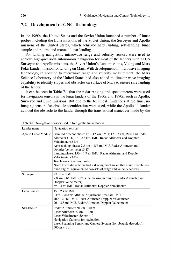
It can be seen in Table 7.1 that the radar ranging and speedometers were used
for navigation sensors in the lunar landers of the 1960s and 1970s, such as Apollo,
Surveyor and Luna missions. But due to the technical limitations at the time, no
imaging sensors for obstacle identification were used, while the Apollo 11 lander
avoided the obstacle to the lander through the translational maneuver made by the
Table 7.1 Navigation sensors used in foreign the lunar landers
Lander name
Navigation sensors
Apollo Lunar Module Powered descent phase: 15 ~ 12 km, IMU; 12 ~ 7 km, IMU and Radar
Altimeter (1-D); 7 ~ 2.3 km, IMU, Radar Altimeter and Doppler
Velocimeter (3-D)
Approaching phase: 2.3 km ~ 156 m, IMU, Radar Altimeter and
Doppler Velocimeter (3-D)
Landing phase: 156 ~ 1.7 m, IMU, Radar Altimeter and Doppler
Velocimeter (3-D)
Touchdown: 7 ~ 0 m, probe
Note: The radar antenna had a driving mechanism that could switch two
fixed angles, equivalent to two sets of range and velocity sensors
Surveyor
~7.8 km: IMU
7.8 km ~ h*: IMU (h* is the maximum range of Radar Altimeter and
Doppler Velocimeter)
h* ~ 4 m: IMU, Radar Altimeter, Doppler Velocimeter
Luna Lander
15 ~ 2 km: IMU
2 km ~ 700 m: Attitude Adjustment, free fall, IMU
700 ~ 20 m: IMU, Radar Altimeter, Doppler Velocimeter
20 ~ 3.5 m: IMU, Radar Altimeter, Doppler Velocimeter
SELENE-2
Radar Altimeter: 50 km ~ 50 m
Laser Altimeter: 5 km ~ 10 m
Laser Velocimeter: 50 m/s ~ 0
Navigation Camera: for navigation
Laser Scanning Sensor and Camera System (for obstacle detection):
500 m ~ 1 m
7 Guidance, Navigation and Control Technology …
7.2 Development of GNC Technology
In the 1960s, the United States and the Soviet Union launched a number of lunar
probes including the Luna missions of the Soviet Union, the Surveyor and Apollo
missions of the United States, which achieved hard landing, soft-landing, lunar
sample and return, and manned lunar landing.
For landing navigation, microwave range and velocity sensors were used to
achieve high-precision autonomous navigation for most of the landers such as US
Surveyor and Apollo missions, the Soviet Union’s Luna missions, Viking and Mars
Polar Lander mission for landing on Mars. With development of microwave imaging
technology, in addition to microwave range and velocity measurement, the Mars
Science Laboratory of the United States had also added millimeter wave imaging
capability to identify slopes and obstacles on surface of Mars to ensure safe landing
of the lander.
It can be seen in Table 7.1 that the radar ranging and speedometers were used
for navigation sensors in the lunar landers of the 1960s and 1970s, such as Apollo,
Surveyor and Luna missions. But due to the technical limitations at the time, no
imaging sensors for obstacle identification were used, while the Apollo 11 lander
avoided the obstacle to the lander through the translational maneuver made by the
Table 7.1 Navigation sensors used in foreign the lunar landers
Lander name
Navigation sensors
Apollo Lunar Module Powered descent phase: 15 ~ 12 km, IMU; 12 ~ 7 km, IMU and Radar
Altimeter (1-D); 7 ~ 2.3 km, IMU, Radar Altimeter and Doppler
Velocimeter (3-D)
Approaching phase: 2.3 km ~ 156 m, IMU, Radar Altimeter and
Doppler Velocimeter (3-D)
Landing phase: 156 ~ 1.7 m, IMU, Radar Altimeter and Doppler
Velocimeter (3-D)
Touchdown: 7 ~ 0 m, probe
Note: The radar antenna had a driving mechanism that could switch two
fixed angles, equivalent to two sets of range and velocity sensors
Surveyor
~7.8 km: IMU
7.8 km ~ h*: IMU (h* is the maximum range of Radar Altimeter and
Doppler Velocimeter)
h* ~ 4 m: IMU, Radar Altimeter, Doppler Velocimeter
Luna Lander
15 ~ 2 km: IMU
2 km ~ 700 m: Attitude Adjustment, free fall, IMU
700 ~ 20 m: IMU, Radar Altimeter, Doppler Velocimeter
20 ~ 3.5 m: IMU, Radar Altimeter, Doppler Velocimeter
SELENE-2
Radar Altimeter: 50 km ~ 50 m
Laser Altimeter: 5 km ~ 10 m
Laser Velocimeter: 50 m/s ~ 0
Navigation Camera: for navigation
Laser Scanning Sensor and Camera System (for obstacle detection):
500 m ~ 1 m