

6.4 Design Methodology
215
Charge Shunt
Module
Balance Module
Battery
Packs of
Lunar
Lander
Hibernation
/Awakening
module
Discharge
Module
Bus+
BusCapacitor
Array
Shunt Module
Solar Arrays
×4
×4
Battery
Packs of
Lunar
Rover
Charge
Switch
Backup
Discharge
module
Power Controller of Lunar Lander
...
Awakening
Load
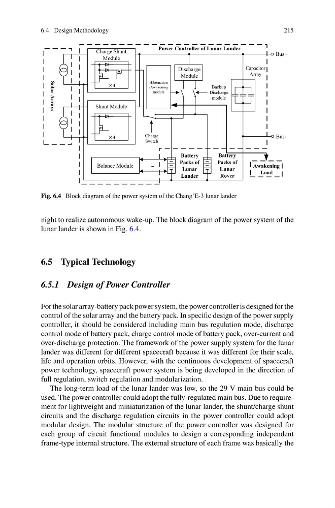
Fig. 6.4 Block diagram of the power system of the Chang’E-3 lunar lander
night to realize autonomous wake-up. The block diagram of the power system of the
lunar lander is shown in Fig. 6.4.
6.5 Typical Technology
6.5.1 Design of Power Controller
For the solar array-battery pack power system, the power controller is designed for the
control of the solar array and the battery pack. In specific design of the power supply
controller, it should be considered including main bus regulation mode, discharge
control mode of battery pack, charge control mode of battery pack, over-current and
over-discharge protection. The framework of the power supply system for the lunar
lander was different for different spacecraft because it was different for their scale,
life and operation orbits. However, with the continuous development of spacecraft
power technology, spacecraft power system is being developed in the direction of
full regulation, switch regulation and modularization.
The long-term load of the lunar lander was low, so the 29 V main bus could be
used. The power controller could adopt the fully-regulated main bus. Due to requirement for lightweight and miniaturization of the lunar lander, the shunt/charge shunt
circuits and the discharge regulation circuits in the power controller could adopt
modular design. The modular structure of the power controller was designed for
each group of circuit functional modules to design a corresponding independent
frame-type internal structure. The external structure of each frame was basically the
215
Charge Shunt
Module
Balance Module
Battery
Packs of
Lunar
Lander
Hibernation
/Awakening
module
Discharge
Module
Bus+
BusCapacitor
Array
Shunt Module
Solar Arrays
×4
×4
Battery
Packs of
Lunar
Rover
Charge
Switch
Backup
Discharge
module
Power Controller of Lunar Lander
...
Awakening
Load
Fig. 6.4 Block diagram of the power system of the Chang’E-3 lunar lander
night to realize autonomous wake-up. The block diagram of the power system of the
lunar lander is shown in Fig. 6.4.
6.5 Typical Technology
6.5.1 Design of Power Controller
For the solar array-battery pack power system, the power controller is designed for the
control of the solar array and the battery pack. In specific design of the power supply
controller, it should be considered including main bus regulation mode, discharge
control mode of battery pack, charge control mode of battery pack, over-current and
over-discharge protection. The framework of the power supply system for the lunar
lander was different for different spacecraft because it was different for their scale,
life and operation orbits. However, with the continuous development of spacecraft
power technology, spacecraft power system is being developed in the direction of
full regulation, switch regulation and modularization.
The long-term load of the lunar lander was low, so the 29 V main bus could be
used. The power controller could adopt the fully-regulated main bus. Due to requirement for lightweight and miniaturization of the lunar lander, the shunt/charge shunt
circuits and the discharge regulation circuits in the power controller could adopt
modular design. The modular structure of the power controller was designed for
each group of circuit functional modules to design a corresponding independent
frame-type internal structure. The external structure of each frame was basically the