

6.4 Design Methodology
209
In order to calculate the power output of the solar array accurately, the error of
landing attitude should be considered. When the occlusion of the solar array was
analyzed, the maximum occlusion area of the solar array and the maximum solar
incident angle could be analyzed respectively to simplify the calculation. When the
maximum occlusion area of the solar array was calculated, the occlusion area under
different solar elevation and azimuth should be analyzed with bias of landing attitude.
When the maximum solar incident angle of the solar array was analyzed, the incident
angle under different solar elevation and azimuth should also be analyzed.
3. Analysis of Maximum Solar Incident Angle of Solar Array
When the lunar lander was working on the moon, it was necessary to adjust the angle
of deployment of the solar array according to the solar elevation in order to achieve
the maximum power output. Due to the limitation of the landing site, the local solar
elevation angle was relatively low, and the solar incident angle of the solar array was
relatively large, and the power output of the solar array at a large solar incident angle
should be analyzed.
For example, the deployed angle of ± Y solar array of the Chang’E-3 lunar lander
was from 20° to 245°. The angle was 180° when the plane of the solar array was
parallel to the local horizontal plane. The maximum deployed angle of the solar array
was 245°.
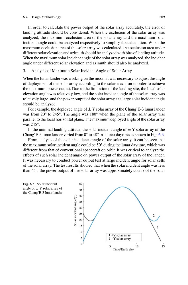
In the nominal landing attitude, the solar incident angle of ± Y solar array of the
Chang’E-3 lunar lander varied from 0° to 48° in a lunar daytime as shown in Fig. 6.3.
From analysis of the solar incidence angle of the solar array, it can be seen that
the maximum solar incident angle could be 50° during the lunar daytime, which was
different from that of conventional spacecraft on orbit. It was critical to analyze the
effects of such solar incident angle on power output of the solar array of the lander.
It was necessary to conduct power output test at large incident angle for solar cells
of the solar array. The test results showed that when the solar incident angle was less
than 45°, the power output of the solar array was approximately cosine of the solar
Fig. 6.3 Solar incident
angle of ± Y solar array of
the Chang’E-3 lunar lander
209
In order to calculate the power output of the solar array accurately, the error of
landing attitude should be considered. When the occlusion of the solar array was
analyzed, the maximum occlusion area of the solar array and the maximum solar
incident angle could be analyzed respectively to simplify the calculation. When the
maximum occlusion area of the solar array was calculated, the occlusion area under
different solar elevation and azimuth should be analyzed with bias of landing attitude.
When the maximum solar incident angle of the solar array was analyzed, the incident
angle under different solar elevation and azimuth should also be analyzed.
3. Analysis of Maximum Solar Incident Angle of Solar Array
When the lunar lander was working on the moon, it was necessary to adjust the angle
of deployment of the solar array according to the solar elevation in order to achieve
the maximum power output. Due to the limitation of the landing site, the local solar
elevation angle was relatively low, and the solar incident angle of the solar array was
relatively large, and the power output of the solar array at a large solar incident angle
should be analyzed.
For example, the deployed angle of ± Y solar array of the Chang’E-3 lunar lander
was from 20° to 245°. The angle was 180° when the plane of the solar array was
parallel to the local horizontal plane. The maximum deployed angle of the solar array
was 245°.
In the nominal landing attitude, the solar incident angle of ± Y solar array of the
Chang’E-3 lunar lander varied from 0° to 48° in a lunar daytime as shown in Fig. 6.3.
From analysis of the solar incidence angle of the solar array, it can be seen that
the maximum solar incident angle could be 50° during the lunar daytime, which was
different from that of conventional spacecraft on orbit. It was critical to analyze the
effects of such solar incident angle on power output of the solar array of the lander.
It was necessary to conduct power output test at large incident angle for solar cells
of the solar array. The test results showed that when the solar incident angle was less
than 45°, the power output of the solar array was approximately cosine of the solar
Fig. 6.3 Solar incident
angle of ± Y solar array of
the Chang’E-3 lunar lander