

5.5 Typical Technologies
181
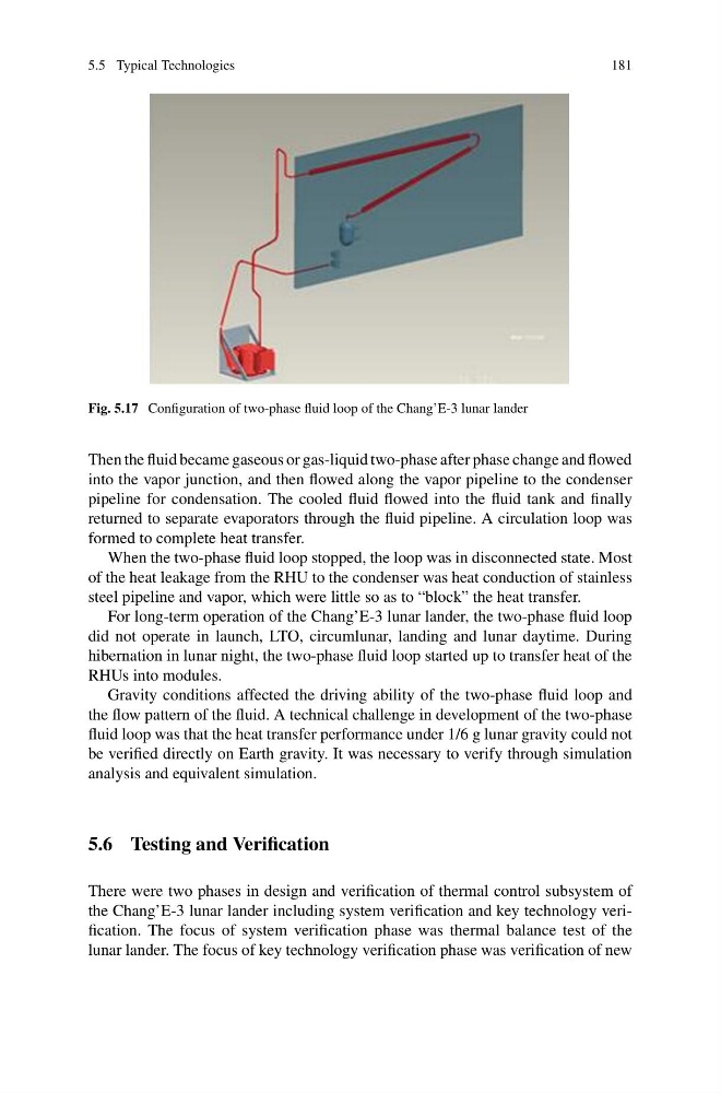
Fig. 5.17 Configuration of two-phase fluid loop of the Chang’E-3 lunar lander
Then the fluid became gaseous or gas-liquid two-phase after phase change and flowed
into the vapor junction, and then flowed along the vapor pipeline to the condenser
pipeline for condensation. The cooled fluid flowed into the fluid tank and finally
returned to separate evaporators through the fluid pipeline. A circulation loop was
formed to complete heat transfer.
When the two-phase fluid loop stopped, the loop was in disconnected state. Most
of the heat leakage from the RHU to the condenser was heat conduction of stainless
steel pipeline and vapor, which were little so as to “block” the heat transfer.
For long-term operation of the Chang’E-3 lunar lander, the two-phase fluid loop
did not operate in launch, LTO, circumlunar, landing and lunar daytime. During
hibernation in lunar night, the two-phase fluid loop started up to transfer heat of the
RHUs into modules.
Gravity conditions affected the driving ability of the two-phase fluid loop and
the flow pattern of the fluid. A technical challenge in development of the two-phase
fluid loop was that the heat transfer performance under 1/6 g lunar gravity could not
be verified directly on Earth gravity. It was necessary to verify through simulation
analysis and equivalent simulation.
5.6 Testing and Verification
There were two phases in design and verification of thermal control subsystem of
the Chang’E-3 lunar lander including system verification and key technology verification. The focus of system verification phase was thermal balance test of the
lunar lander. The focus of key technology verification phase was verification of new
181
Fig. 5.17 Configuration of two-phase fluid loop of the Chang’E-3 lunar lander
Then the fluid became gaseous or gas-liquid two-phase after phase change and flowed
into the vapor junction, and then flowed along the vapor pipeline to the condenser
pipeline for condensation. The cooled fluid flowed into the fluid tank and finally
returned to separate evaporators through the fluid pipeline. A circulation loop was
formed to complete heat transfer.
When the two-phase fluid loop stopped, the loop was in disconnected state. Most
of the heat leakage from the RHU to the condenser was heat conduction of stainless
steel pipeline and vapor, which were little so as to “block” the heat transfer.
For long-term operation of the Chang’E-3 lunar lander, the two-phase fluid loop
did not operate in launch, LTO, circumlunar, landing and lunar daytime. During
hibernation in lunar night, the two-phase fluid loop started up to transfer heat of the
RHUs into modules.
Gravity conditions affected the driving ability of the two-phase fluid loop and
the flow pattern of the fluid. A technical challenge in development of the two-phase
fluid loop was that the heat transfer performance under 1/6 g lunar gravity could not
be verified directly on Earth gravity. It was necessary to verify through simulation
analysis and equivalent simulation.
5.6 Testing and Verification
There were two phases in design and verification of thermal control subsystem of
the Chang’E-3 lunar lander including system verification and key technology verification. The focus of system verification phase was thermal balance test of the
lunar lander. The focus of key technology verification phase was verification of new