

5.5 Typical Technologies
173
Fig. 5.10 Relation between the lunar lander structure and heat transfer system of variable thermal
conductivity
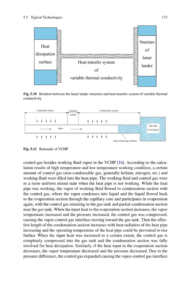
Fig. 5.11 Rationale of VCHP
control gas besides working fluid vapor in the VCHP [16]. According to the calculation results of high temperature and low temperature working condition, a certain
amount of control gas (non-condensable gas, generally helium, nitrogen, etc.) and
working fluid were filled into the heat pipe. The working fluid and control gas were
in a more uniform mixed state when the heat pipe is not working. While the heat
pipe was working, the vapor of working fluid flowed to condensation section with
the control gas, where the vapor condenses into liquid and the liquid flowed back
to the evaporation section through the capillary core and participates in evaporation
again, with the control gas retaining in the gas tank and partial condensation section
near the gas tank. When the input heat to the evaporation section increases, the vapor
temperature increased and the pressure increased, the control gas was compressed,
causing the vapor-control gas interface moving toward the gas tank. Then the effective length of the condensation section increases with heat radiation of the heat pipe
increasing and the operating temperature of the heat pipe could be prevented to rise
further. When the input heat was increased to a certain extent, the control gas is
completely compressed into the gas tank and the condensation section was fully
involved for heat dissipation. Similarly, if the heat input to the evaporation section
decreases, the vapor temperature decreased and the pressure decreased. Due to the
pressure difference, the control gas expanded causing the vapor-control gas interface
173
Fig. 5.10 Relation between the lunar lander structure and heat transfer system of variable thermal
conductivity
Fig. 5.11 Rationale of VCHP
control gas besides working fluid vapor in the VCHP [16]. According to the calculation results of high temperature and low temperature working condition, a certain
amount of control gas (non-condensable gas, generally helium, nitrogen, etc.) and
working fluid were filled into the heat pipe. The working fluid and control gas were
in a more uniform mixed state when the heat pipe is not working. While the heat
pipe was working, the vapor of working fluid flowed to condensation section with
the control gas, where the vapor condenses into liquid and the liquid flowed back
to the evaporation section through the capillary core and participates in evaporation
again, with the control gas retaining in the gas tank and partial condensation section
near the gas tank. When the input heat to the evaporation section increases, the vapor
temperature increased and the pressure increased, the control gas was compressed,
causing the vapor-control gas interface moving toward the gas tank. Then the effective length of the condensation section increases with heat radiation of the heat pipe
increasing and the operating temperature of the heat pipe could be prevented to rise
further. When the input heat was increased to a certain extent, the control gas is
completely compressed into the gas tank and the condensation section was fully
involved for heat dissipation. Similarly, if the heat input to the evaporation section
decreases, the vapor temperature decreased and the pressure decreased. Due to the
pressure difference, the control gas expanded causing the vapor-control gas interface