

18 Fault Isolation and Failure Analysis of 3D Packaging
587
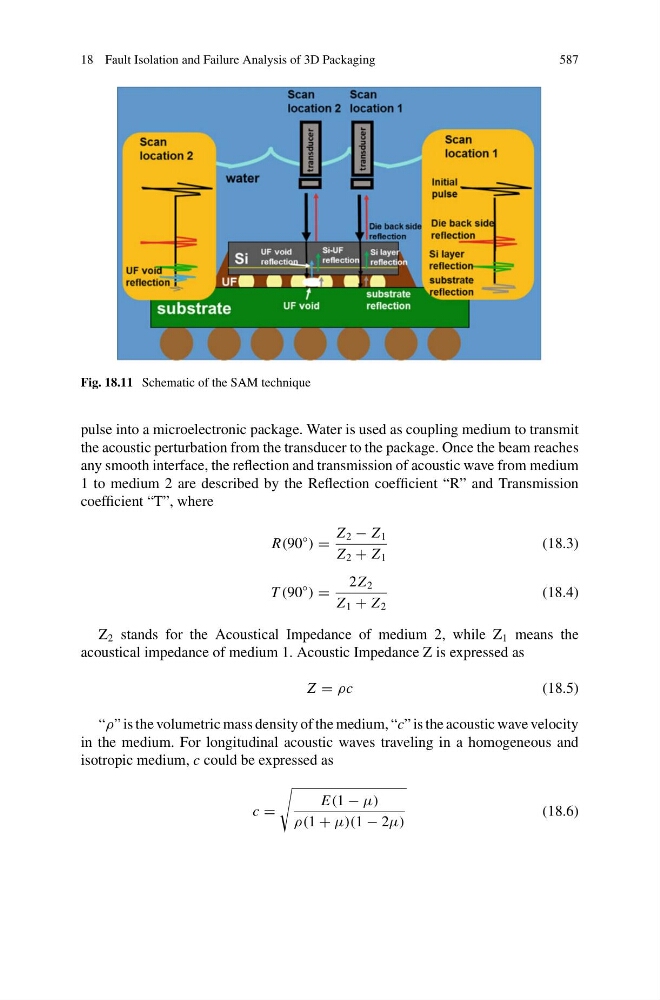
Fig. 18.11 Schematic of the SAM technique
pulse into a microelectronic package. Water is used as coupling medium to transmit
the acoustic perturbation from the transducer to the package. Once the beam reaches
any smooth interface, the reflection and transmission of acoustic wave from medium
1 to medium 2 are described by the Reflection coefficient “R” and Transmission
coefficient “T”, where
R(90
◦
) =
Z 2 − Z 1
Z 2 + Z 1
(18.3)
T (90
◦
) =
2Z 2
Z 1 + Z 2
(18.4)
Z 2 stands for the Acoustical Impedance of medium 2, while Z 1 means the
acoustical impedance of medium 1. Acoustic Impedance Z is expressed as
Z = ρc
(18.5)
“ρ” is the volumetric mass density of the medium, “c” is the acoustic wave velocity
in the medium. For longitudinal acoustic waves traveling in a homogeneous and
isotropic medium, c could be expressed as
c =
E(1 − μ)
ρ(1 + μ)(1 − 2μ)
(18.6)