

4
P. R. Willmott
L IN A C
ID
Insertion
device
~ 1 0 0 p s
ring
Storage
Bend
achromat
Booster
ring
e−gun
RF
Front end
Optics
Experimental
hutch
beamline
BM
beamline
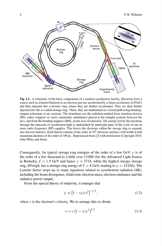
Fig. 1.2 A schematic of the basic components of a modern synchrotron facility. Electrons from a
source such as a heated filament in an electron gun are accelerated by a linear accelerator (LINAC)
and then injected into a booster ring, where they are further accelerated. They are then further
injected into the so-called storage ring. There, they are maintained in a closed path using bendingmagnet achromats at arc sections. The beamlines use the radiation emitted from insertion devices
(IDs, either wigglers or, more commonly, undulators) placed at the straight sections between the
arcs, and from the bending magnets (BM), on the axes of emission. The energy lost by the electrons
through the emission of synchrotron light is replenished by particular parts of the cycle of one or
more radio frequency (RF) supplies. This forces the electrons within the storage ring to separate
into discrete bunches. Each bunch contains of the order of 10 9 electrons and has a full width at half
maximum duration of the order of 100 ps. Reproduced from [3] with permission (Copyright 2019,
John Wiley and Sons)
Consequently, for typical storage ring energies of the order of a few GeV, γ is of
the order of a few thousand to a little over 15 000 (for the Advanced Light Source
in Berkeley, E = 1.9 GeV and hence γ = 3718, while the highest energy storage
ring, SPring8, has a storage ring energy of E = 8 GeV, leading to γ = 15 656). The
Lorentz factor crops up in many equations related to synchrotron radiation (SR),
including the beam divergence, relativistic electron mass, electron emittance and the
radiative power output.
From the special theory of relativity, it emerges that
γ =
1 − (v/c)
2
−1/2 ,
(1.2)
where v is the electron’s velocity. We re-arrange this to obtain
v = c
1 − 1/γ
2
1/2 .
(1.3)
P. R. Willmott
L IN A C
ID
Insertion
device
~ 1 0 0 p s
ring
Storage
Bend
achromat
Booster
ring
e−gun
RF
Front end
Optics
Experimental
hutch
beamline
BM
beamline
Fig. 1.2 A schematic of the basic components of a modern synchrotron facility. Electrons from a
source such as a heated filament in an electron gun are accelerated by a linear accelerator (LINAC)
and then injected into a booster ring, where they are further accelerated. They are then further
injected into the so-called storage ring. There, they are maintained in a closed path using bendingmagnet achromats at arc sections. The beamlines use the radiation emitted from insertion devices
(IDs, either wigglers or, more commonly, undulators) placed at the straight sections between the
arcs, and from the bending magnets (BM), on the axes of emission. The energy lost by the electrons
through the emission of synchrotron light is replenished by particular parts of the cycle of one or
more radio frequency (RF) supplies. This forces the electrons within the storage ring to separate
into discrete bunches. Each bunch contains of the order of 10 9 electrons and has a full width at half
maximum duration of the order of 100 ps. Reproduced from [3] with permission (Copyright 2019,
John Wiley and Sons)
Consequently, for typical storage ring energies of the order of a few GeV, γ is of
the order of a few thousand to a little over 15 000 (for the Advanced Light Source
in Berkeley, E = 1.9 GeV and hence γ = 3718, while the highest energy storage
ring, SPring8, has a storage ring energy of E = 8 GeV, leading to γ = 15 656). The
Lorentz factor crops up in many equations related to synchrotron radiation (SR),
including the beam divergence, relativistic electron mass, electron emittance and the
radiative power output.
From the special theory of relativity, it emerges that
γ =
1 − (v/c)
2
−1/2 ,
(1.2)
where v is the electron’s velocity. We re-arrange this to obtain
v = c
1 − 1/γ
2
1/2 .
(1.3)