

44 Acoustic Emission Characteristics of Defects …
509
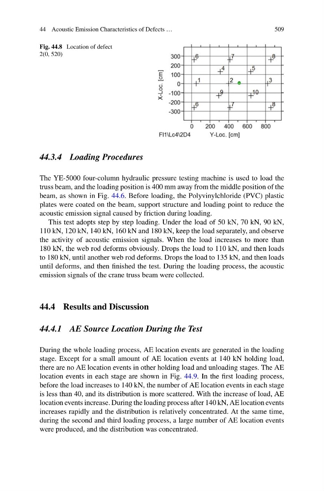
Fig. 44.8 Location of defect
2(0, 520)
44.3.4 Loading Procedures
The YE-5000 four-column hydraulic pressure testing machine is used to load the
truss beam, and the loading position is 400 mm away from the middle position of the
beam, as shown in Fig. 44.6. Before loading, the Polyvinylchloride (PVC) plastic
plates were coated on the beam, support structure and loading point to reduce the
acoustic emission signal caused by friction during loading.
This test adopts step by step loading. Under the load of 50 kN, 70 kN, 90 kN,
110 kN, 120 kN, 140 kN, 160 kN and 180 kN, keep the load separately, and observe
the activity of acoustic emission signals. When the load increases to more than
180 kN, the web rod deforms obviously. Drops the load to 110 kN, and then loads
to 180 kN, until another web rod deforms. Drops the load to 135 kN, and then loads
until deforms, and then finished the test. During the loading process, the acoustic
emission signals of the crane truss beam were collected.
44.4 Results and Discussion
44.4.1 AE Source Location During the Test
During the whole loading process, AE location events are generated in the loading
stage. Except for a small amount of AE location events at 140 kN holding load,
there are no AE location events in other holding load and unloading stages. The AE
location events in each stage are shown in Fig. 44.9. In the first loading process,
before the load increases to 140 kN, the number of AE location events in each stage
is less than 40, and its distribution is more scattered. With the increase of load, AE
location events increase. During the loading process after 140 kN, AE location events
increases rapidly and the distribution is relatively concentrated. At the same time,
during the second and third loading process, a large number of AE location events
were produced, and the distribution was concentrated.
509
Fig. 44.8 Location of defect
2(0, 520)
44.3.4 Loading Procedures
The YE-5000 four-column hydraulic pressure testing machine is used to load the
truss beam, and the loading position is 400 mm away from the middle position of the
beam, as shown in Fig. 44.6. Before loading, the Polyvinylchloride (PVC) plastic
plates were coated on the beam, support structure and loading point to reduce the
acoustic emission signal caused by friction during loading.
This test adopts step by step loading. Under the load of 50 kN, 70 kN, 90 kN,
110 kN, 120 kN, 140 kN, 160 kN and 180 kN, keep the load separately, and observe
the activity of acoustic emission signals. When the load increases to more than
180 kN, the web rod deforms obviously. Drops the load to 110 kN, and then loads
to 180 kN, until another web rod deforms. Drops the load to 135 kN, and then loads
until deforms, and then finished the test. During the loading process, the acoustic
emission signals of the crane truss beam were collected.
44.4 Results and Discussion
44.4.1 AE Source Location During the Test
During the whole loading process, AE location events are generated in the loading
stage. Except for a small amount of AE location events at 140 kN holding load,
there are no AE location events in other holding load and unloading stages. The AE
location events in each stage are shown in Fig. 44.9. In the first loading process,
before the load increases to 140 kN, the number of AE location events in each stage
is less than 40, and its distribution is more scattered. With the increase of load, AE
location events increase. During the loading process after 140 kN, AE location events
increases rapidly and the distribution is relatively concentrated. At the same time,
during the second and third loading process, a large number of AE location events
were produced, and the distribution was concentrated.