

40 Localization of Acoustic Emission Sources …
451
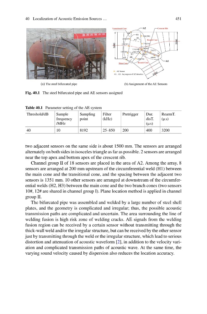
Fig. 40.1 The steel bifurcated pipe and AE sensors assigned
Table 40.1 Parameter setting of the AE system
Threshold/dB
Sample
frequency
/MHz
Sampling
point
Filter
(kHz)
Pretrigger
Dur.
disT.
(μs)
RearmT.
(μs)
40
10
8192
25–850
200
400
3200
two adjacent sensors on the same side is about 1500 mm. The sensors are arranged
alternately on both sides in isosceles triangle as far as possible. 2 sensors are arranged
near the top apex and bottom apex of the crescent rib.
Channel group II of 18 sensors are placed in the area of A2. Among the array, 8
sensors are arranged at 200 mm upstream of the circumferential weld (H1) between
the main cone and the transitional cone, and the spacing between the adjacent two
sensors is 1351 mm. 10 other sensors are arranged at downstream of the circumferential welds (H2, H3) between the main cone and the two branch cones (two sensors
10#, 12# are shared in channel group I). Plane location method is applied in channel
group II.
The bifurcated pipe was assembled and welded by a large number of steel shell
plates, and the geometry is complicated and irregular; thus, the possible acoustic
transmission paths are complicated and uncertain. The area surrounding the line of
welding fusion is high risk zone of welding cracks. AE signals from the welding
fusion region can be received by a certain sensor without transmitting through the
thick-wall weld and/or the irregular structure, but can be received by the other sensor
just by transmitting through the weld or the irregular structure, which lead to serious
distortion and attenuation of acoustic waveform [2], in addition to the velocity variation and complicated transmission paths of acoustic wave. At the same time, the
varying sound velocity caused by dispersion also reduces the location accuracy.
451
Fig. 40.1 The steel bifurcated pipe and AE sensors assigned
Table 40.1 Parameter setting of the AE system
Threshold/dB
Sample
frequency
/MHz
Sampling
point
Filter
(kHz)
Pretrigger
Dur.
disT.
(μs)
RearmT.
(μs)
40
10
8192
25–850
200
400
3200
two adjacent sensors on the same side is about 1500 mm. The sensors are arranged
alternately on both sides in isosceles triangle as far as possible. 2 sensors are arranged
near the top apex and bottom apex of the crescent rib.
Channel group II of 18 sensors are placed in the area of A2. Among the array, 8
sensors are arranged at 200 mm upstream of the circumferential weld (H1) between
the main cone and the transitional cone, and the spacing between the adjacent two
sensors is 1351 mm. 10 other sensors are arranged at downstream of the circumferential welds (H2, H3) between the main cone and the two branch cones (two sensors
10#, 12# are shared in channel group I). Plane location method is applied in channel
group II.
The bifurcated pipe was assembled and welded by a large number of steel shell
plates, and the geometry is complicated and irregular; thus, the possible acoustic
transmission paths are complicated and uncertain. The area surrounding the line of
welding fusion is high risk zone of welding cracks. AE signals from the welding
fusion region can be received by a certain sensor without transmitting through the
thick-wall weld and/or the irregular structure, but can be received by the other sensor
just by transmitting through the weld or the irregular structure, which lead to serious
distortion and attenuation of acoustic waveform [2], in addition to the velocity variation and complicated transmission paths of acoustic wave. At the same time, the
varying sound velocity caused by dispersion also reduces the location accuracy.