

Exploring Non-covalent Interactions by Jet-Cooled Electronic …
67
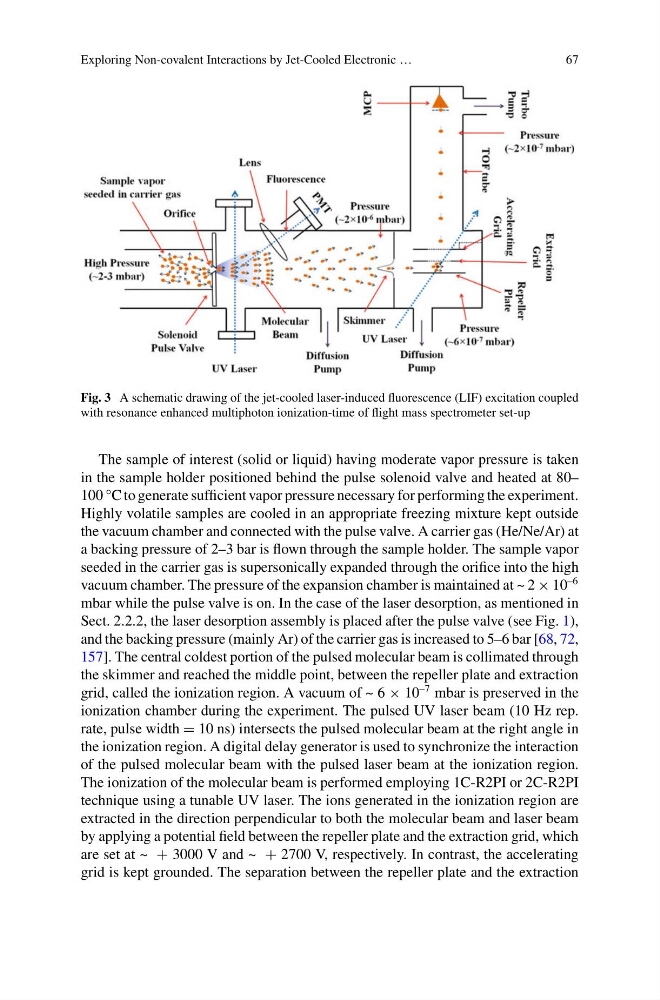
Fig. 3 A schematic drawing of the jet-cooled laser-induced fluorescence (LIF) excitation coupled
with resonance enhanced multiphoton ionization-time of flight mass spectrometer set-up
The sample of interest (solid or liquid) having moderate vapor pressure is taken
in the sample holder positioned behind the pulse solenoid valve and heated at 80–
100 °C to generate sufficient vapor pressure necessary for performing the experiment.
Highly volatile samples are cooled in an appropriate freezing mixture kept outside
the vacuum chamber and connected with the pulse valve. A carrier gas (He/Ne/Ar) at
a backing pressure of 2–3 bar is flown through the sample holder. The sample vapor
seeded in the carrier gas is supersonically expanded through the orifice into the high
vacuum chamber. The pressure of the expansion chamber is maintained at ~ 2 × 10
–6
mbar while the pulse valve is on. In the case of the laser desorption, as mentioned in
Sect. 2.2.2, the laser desorption assembly is placed after the pulse valve (see Fig. 1),
and the backing pressure (mainly Ar) of the carrier gas is increased to 5–6 bar [68, 72,
157]. The central coldest portion of the pulsed molecular beam is collimated through
the skimmer and reached the middle point, between the repeller plate and extraction
grid, called the ionization region. A vacuum of ~ 6 × 10
–7 mbar is preserved in the
ionization chamber during the experiment. The pulsed UV laser beam (10 Hz rep.
rate, pulse width = 10 ns) intersects the pulsed molecular beam at the right angle in
the ionization region. A digital delay generator is used to synchronize the interaction
of the pulsed molecular beam with the pulsed laser beam at the ionization region.
The ionization of the molecular beam is performed employing 1C-R2PI or 2C-R2PI
technique using a tunable UV laser. The ions generated in the ionization region are
extracted in the direction perpendicular to both the molecular beam and laser beam
by applying a potential field between the repeller plate and the extraction grid, which
are set at ~ + 3000 V and ~ + 2700 V, respectively. In contrast, the accelerating
grid is kept grounded. The separation between the repeller plate and the extraction
67
Fig. 3 A schematic drawing of the jet-cooled laser-induced fluorescence (LIF) excitation coupled
with resonance enhanced multiphoton ionization-time of flight mass spectrometer set-up
The sample of interest (solid or liquid) having moderate vapor pressure is taken
in the sample holder positioned behind the pulse solenoid valve and heated at 80–
100 °C to generate sufficient vapor pressure necessary for performing the experiment.
Highly volatile samples are cooled in an appropriate freezing mixture kept outside
the vacuum chamber and connected with the pulse valve. A carrier gas (He/Ne/Ar) at
a backing pressure of 2–3 bar is flown through the sample holder. The sample vapor
seeded in the carrier gas is supersonically expanded through the orifice into the high
vacuum chamber. The pressure of the expansion chamber is maintained at ~ 2 × 10
–6
mbar while the pulse valve is on. In the case of the laser desorption, as mentioned in
Sect. 2.2.2, the laser desorption assembly is placed after the pulse valve (see Fig. 1),
and the backing pressure (mainly Ar) of the carrier gas is increased to 5–6 bar [68, 72,
157]. The central coldest portion of the pulsed molecular beam is collimated through
the skimmer and reached the middle point, between the repeller plate and extraction
grid, called the ionization region. A vacuum of ~ 6 × 10
–7 mbar is preserved in the
ionization chamber during the experiment. The pulsed UV laser beam (10 Hz rep.
rate, pulse width = 10 ns) intersects the pulsed molecular beam at the right angle in
the ionization region. A digital delay generator is used to synchronize the interaction
of the pulsed molecular beam with the pulsed laser beam at the ionization region.
The ionization of the molecular beam is performed employing 1C-R2PI or 2C-R2PI
technique using a tunable UV laser. The ions generated in the ionization region are
extracted in the direction perpendicular to both the molecular beam and laser beam
by applying a potential field between the repeller plate and the extraction grid, which
are set at ~ + 3000 V and ~ + 2700 V, respectively. In contrast, the accelerating
grid is kept grounded. The separation between the repeller plate and the extraction