

6
H. Kaur et al.
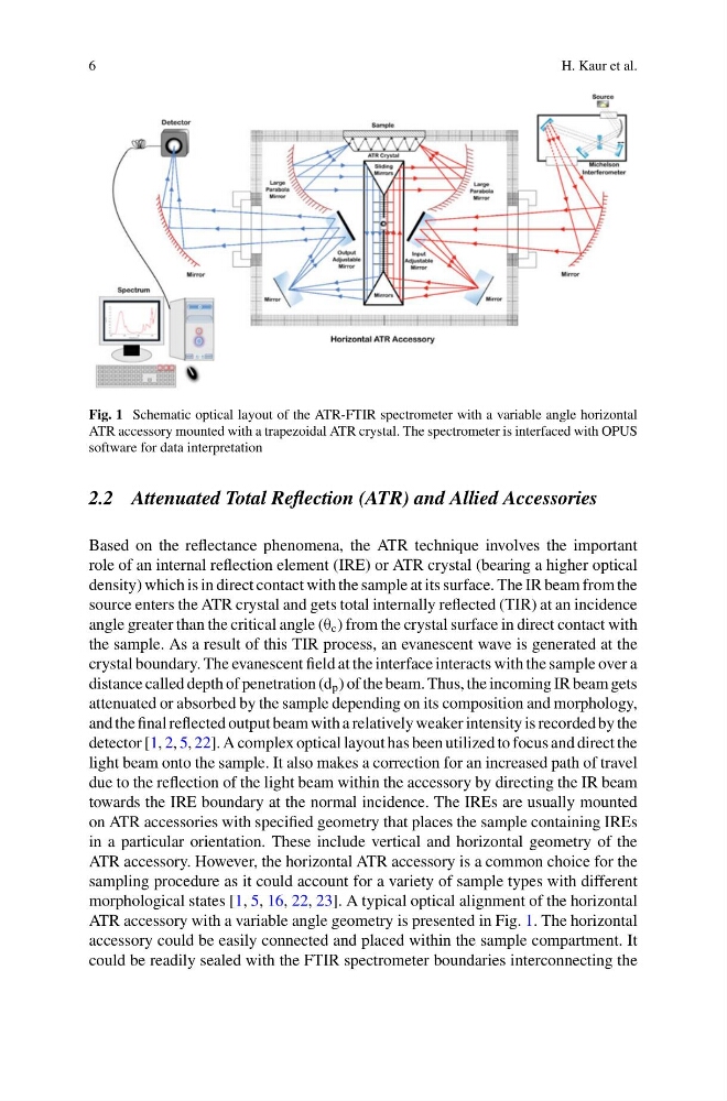
Fig. 1 Schematic optical layout of the ATR-FTIR spectrometer with a variable angle horizontal
ATR accessory mounted with a trapezoidal ATR crystal. The spectrometer is interfaced with OPUS
software for data interpretation
2.2 Attenuated Total Reflection (ATR) and Allied Accessories
Based on the reflectance phenomena, the ATR technique involves the important
role of an internal reflection element (IRE) or ATR crystal (bearing a higher optical
density) which is in direct contact with the sample at its surface. The IR beam from the
source enters the ATR crystal and gets total internally reflected (TIR) at an incidence
angle greater than the critical angle (θ c ) from the crystal surface in direct contact with
the sample. As a result of this TIR process, an evanescent wave is generated at the
crystal boundary. The evanescent field at the interface interacts with the sample over a
distance called depth of penetration (d p ) of the beam. Thus, the incoming IR beam gets
attenuated or absorbed by the sample depending on its composition and morphology,
and the final reflected output beam with a relatively weaker intensity is recorded by the
detector [1, 2, 5, 22]. A complex optical layout has been utilized to focus and direct the
light beam onto the sample. It also makes a correction for an increased path of travel
due to the reflection of the light beam within the accessory by directing the IR beam
towards the IRE boundary at the normal incidence. The IREs are usually mounted
on ATR accessories with specified geometry that places the sample containing IREs
in a particular orientation. These include vertical and horizontal geometry of the
ATR accessory. However, the horizontal ATR accessory is a common choice for the
sampling procedure as it could account for a variety of sample types with different
morphological states [1, 5, 16, 22, 23]. A typical optical alignment of the horizontal
ATR accessory with a variable angle geometry is presented in Fig. 1. The horizontal
accessory could be easily connected and placed within the sample compartment. It
could be readily sealed with the FTIR spectrometer boundaries interconnecting the
H. Kaur et al.
Fig. 1 Schematic optical layout of the ATR-FTIR spectrometer with a variable angle horizontal
ATR accessory mounted with a trapezoidal ATR crystal. The spectrometer is interfaced with OPUS
software for data interpretation
2.2 Attenuated Total Reflection (ATR) and Allied Accessories
Based on the reflectance phenomena, the ATR technique involves the important
role of an internal reflection element (IRE) or ATR crystal (bearing a higher optical
density) which is in direct contact with the sample at its surface. The IR beam from the
source enters the ATR crystal and gets total internally reflected (TIR) at an incidence
angle greater than the critical angle (θ c ) from the crystal surface in direct contact with
the sample. As a result of this TIR process, an evanescent wave is generated at the
crystal boundary. The evanescent field at the interface interacts with the sample over a
distance called depth of penetration (d p ) of the beam. Thus, the incoming IR beam gets
attenuated or absorbed by the sample depending on its composition and morphology,
and the final reflected output beam with a relatively weaker intensity is recorded by the
detector [1, 2, 5, 22]. A complex optical layout has been utilized to focus and direct the
light beam onto the sample. It also makes a correction for an increased path of travel
due to the reflection of the light beam within the accessory by directing the IR beam
towards the IRE boundary at the normal incidence. The IREs are usually mounted
on ATR accessories with specified geometry that places the sample containing IREs
in a particular orientation. These include vertical and horizontal geometry of the
ATR accessory. However, the horizontal ATR accessory is a common choice for the
sampling procedure as it could account for a variety of sample types with different
morphological states [1, 5, 16, 22, 23]. A typical optical alignment of the horizontal
ATR accessory with a variable angle geometry is presented in Fig. 1. The horizontal
accessory could be easily connected and placed within the sample compartment. It
could be readily sealed with the FTIR spectrometer boundaries interconnecting the