

Overview of Raman Spectroscopy: Fundamental to Applications
155
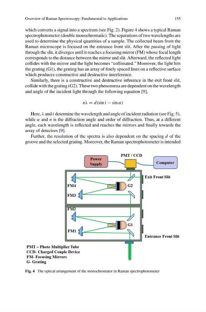
which converts a signal into a spectrum (see Fig. 2). Figure 4 shows a typical Raman
spectrophotometer (double monochromatic). The separations of two wavelengths are
used to determine the physical quantities of a sample. The collected beam from the
Raman microscope is focused on the entrance front slit. After the passing of light
through the slit, it diverges until it reaches a focusing mirror (FM) whose focal length
corresponds to the distance between the mirror and slit. Afterward, the reflected light
collides with the mirror and the light becomes “collimated.” Moreover, the light hits
the grating (G1), the grating has an array of finely spaced lines on a reflective surface
which produces constructive and destructive interference.
Similarly, there is a constructive and destructive inference in the exit front slit,
collide with the grating (G2). These two phenomena are dependent on the wavelength
and angle of the incident light through the following equation [9],
nλ = d(sin i − sin α)
Here, λ and i determine the wavelength and angle of incident radiation (see Fig. 5),
while α and n is the diffraction angle and order of diffraction. Thus, at a different
angle, each wavelength is reflected and reaches the mirrors and finally towards the
array of detectors [9].
Further, the resolution of the spectra is also dependent on the spacing d of the
groove and the selected grating. Moreover, the Raman spectrophotometer is intended
Fig. 4 The optical arrangement of the monochromator in Raman spectrophotometer
155
which converts a signal into a spectrum (see Fig. 2). Figure 4 shows a typical Raman
spectrophotometer (double monochromatic). The separations of two wavelengths are
used to determine the physical quantities of a sample. The collected beam from the
Raman microscope is focused on the entrance front slit. After the passing of light
through the slit, it diverges until it reaches a focusing mirror (FM) whose focal length
corresponds to the distance between the mirror and slit. Afterward, the reflected light
collides with the mirror and the light becomes “collimated.” Moreover, the light hits
the grating (G1), the grating has an array of finely spaced lines on a reflective surface
which produces constructive and destructive interference.
Similarly, there is a constructive and destructive inference in the exit front slit,
collide with the grating (G2). These two phenomena are dependent on the wavelength
and angle of the incident light through the following equation [9],
nλ = d(sin i − sin α)
Here, λ and i determine the wavelength and angle of incident radiation (see Fig. 5),
while α and n is the diffraction angle and order of diffraction. Thus, at a different
angle, each wavelength is reflected and reaches the mirrors and finally towards the
array of detectors [9].
Further, the resolution of the spectra is also dependent on the spacing d of the
groove and the selected grating. Moreover, the Raman spectrophotometer is intended
Fig. 4 The optical arrangement of the monochromator in Raman spectrophotometer