

Broadband Terahertz Spectroscopy
127
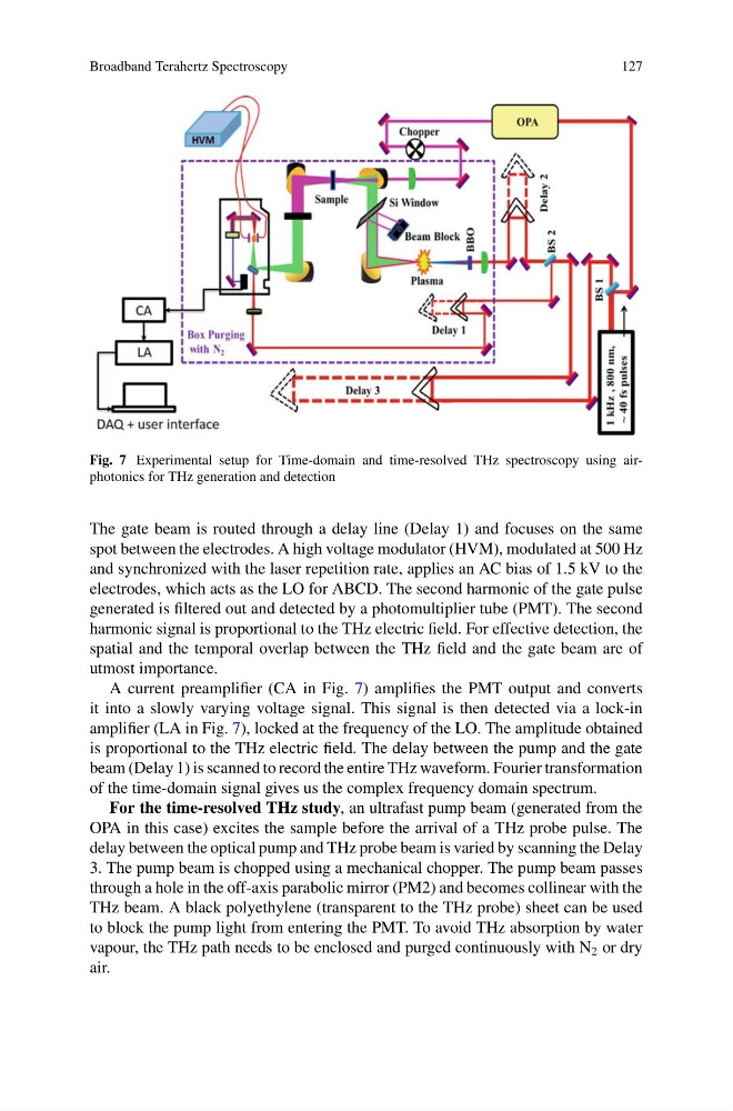
Fig. 7 Experimental setup for Time-domain and time-resolved THz spectroscopy using airphotonics for THz generation and detection
The gate beam is routed through a delay line (Delay 1) and focuses on the same
spot between the electrodes. A high voltage modulator (HVM), modulated at 500 Hz
and synchronized with the laser repetition rate, applies an AC bias of 1.5 kV to the
electrodes, which acts as the LO for ABCD. The second harmonic of the gate pulse
generated is filtered out and detected by a photomultiplier tube (PMT). The second
harmonic signal is proportional to the THz electric field. For effective detection, the
spatial and the temporal overlap between the THz field and the gate beam are of
utmost importance.
A current preamplifier (CA in Fig. 7) amplifies the PMT output and converts
it into a slowly varying voltage signal. This signal is then detected via a lock-in
amplifier (LA in Fig. 7), locked at the frequency of the LO. The amplitude obtained
is proportional to the THz electric field. The delay between the pump and the gate
beam (Delay 1) is scanned to record the entire THz waveform. Fourier transformation
of the time-domain signal gives us the complex frequency domain spectrum.
For the time-resolved THz study, an ultrafast pump beam (generated from the
OPA in this case) excites the sample before the arrival of a THz probe pulse. The
delay between the optical pump and THz probe beam is varied by scanning the Delay
3. The pump beam is chopped using a mechanical chopper. The pump beam passes
through a hole in the off-axis parabolic mirror (PM2) and becomes collinear with the
THz beam. A black polyethylene (transparent to the THz probe) sheet can be used
to block the pump light from entering the PMT. To avoid THz absorption by water
vapour, the THz path needs to be enclosed and purged continuously with N 2 or dry
air.
127
Fig. 7 Experimental setup for Time-domain and time-resolved THz spectroscopy using airphotonics for THz generation and detection
The gate beam is routed through a delay line (Delay 1) and focuses on the same
spot between the electrodes. A high voltage modulator (HVM), modulated at 500 Hz
and synchronized with the laser repetition rate, applies an AC bias of 1.5 kV to the
electrodes, which acts as the LO for ABCD. The second harmonic of the gate pulse
generated is filtered out and detected by a photomultiplier tube (PMT). The second
harmonic signal is proportional to the THz electric field. For effective detection, the
spatial and the temporal overlap between the THz field and the gate beam are of
utmost importance.
A current preamplifier (CA in Fig. 7) amplifies the PMT output and converts
it into a slowly varying voltage signal. This signal is then detected via a lock-in
amplifier (LA in Fig. 7), locked at the frequency of the LO. The amplitude obtained
is proportional to the THz electric field. The delay between the pump and the gate
beam (Delay 1) is scanned to record the entire THz waveform. Fourier transformation
of the time-domain signal gives us the complex frequency domain spectrum.
For the time-resolved THz study, an ultrafast pump beam (generated from the
OPA in this case) excites the sample before the arrival of a THz probe pulse. The
delay between the optical pump and THz probe beam is varied by scanning the Delay
3. The pump beam is chopped using a mechanical chopper. The pump beam passes
through a hole in the off-axis parabolic mirror (PM2) and becomes collinear with the
THz beam. A black polyethylene (transparent to the THz probe) sheet can be used
to block the pump light from entering the PMT. To avoid THz absorption by water
vapour, the THz path needs to be enclosed and purged continuously with N 2 or dry
air.