

46
4 Design Optimization of Micromixers
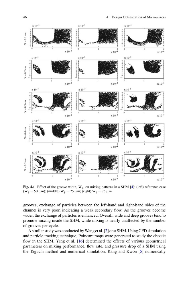
Fig. 4.1 Effect of the groove width, W g , on mixing patterns in a SHM [4]: (left) reference case
(W g = 50 μm); (middle) W g = 25 μm; (right) W g = 75 μm
grooves, exchange of particles between the left-hand and right-hand sides of the
channel is very poor, indicating a weak secondary flow. As the grooves become
wider, the exchange of particles is enhanced. Overall, wide and deep grooves tend to
promote mixing inside the SHM, while mixing is nearly unaffected by the number
of grooves per cycle.
A similar study was conducted by Wang et al. [2] on a SHM. Using CFD simulation
and particle tracking technique, Poincare maps were generated to study the chaotic
flow in the SHM. Yang et al. [16] determined the effects of various geometrical
parameters on mixing performance, flow rate, and pressure drop of a SHM using
the Taguchi method and numerical simulation. Kang and Kwon [5] numerically
4 Design Optimization of Micromixers
Fig. 4.1 Effect of the groove width, W g , on mixing patterns in a SHM [4]: (left) reference case
(W g = 50 μm); (middle) W g = 25 μm; (right) W g = 75 μm
grooves, exchange of particles between the left-hand and right-hand sides of the
channel is very poor, indicating a weak secondary flow. As the grooves become
wider, the exchange of particles is enhanced. Overall, wide and deep grooves tend to
promote mixing inside the SHM, while mixing is nearly unaffected by the number
of grooves per cycle.
A similar study was conducted by Wang et al. [2] on a SHM. Using CFD simulation
and particle tracking technique, Poincare maps were generated to study the chaotic
flow in the SHM. Yang et al. [16] determined the effects of various geometrical
parameters on mixing performance, flow rate, and pressure drop of a SHM using
the Taguchi method and numerical simulation. Kang and Kwon [5] numerically