

3.2 Spectrometer
25
1 mm
SQUID INPUT COIL
Dy 2 Ti 2 O 2
SAMPLE
4 mm
SQUID
6 mm
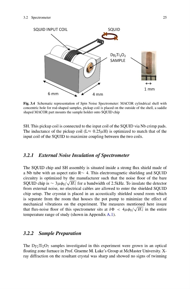
Fig. 3.4 Schematic representation of Spin Noise Spectrometer: MACOR cylindrical shell with
concentric hole for rod-shaped samples, pickup coil is placed on the outside of the shell, a saddle
shaped MACOR part mounts the sample holder onto SQUID chip
SH. This pickup coil is connected to the input coil of the SQUID via Nb crimp pads.
The inductance of the pickup coil (L≈ 0.25μH) is optimized to match that of the
input coil of the SQUID to maximize coupling between the two coils.
3.2.1 External Noise Insulation of Spectrometer
The SQUID chip and SH assembly is situated inside a strong flux shield made of
a Nb tube with an aspect ratio R∼ 4. This electromagnetic shielding and SQUID
circuitry is optimized by the manufacturer such that the noise floor of the bare
SQUID chip is ∼ 3μφ 0 /
√
H z for a bandwidth of 2.5kHz. To insulate the detector
from external noise, no electrical cables are allowed to enter the shielded SQUID
chip setup. The cryostat is placed in an acoustically shielded sound room which
is separate from the room that houses the pot pump to minimize the effect of
mechanical vibrations on the experiment. The measures mentioned here insure
that flux-noise floor of this spectrometer sits at δδ < 4μφ 0 /
√
H z in the entire
temperature range of study (shown in Appendix A.1).
3.2.2 Sample Preparation
The Dy 2 Ti 2 O 7 samples investigated in this experiment were grown in an optical
floating zone furnace in Prof. Graeme M. Luke’s Group at McMaster University. Xray diffraction on the resultant crystal was sharp and showed no signs of twinning
25
1 mm
SQUID INPUT COIL
Dy 2 Ti 2 O 2
SAMPLE
4 mm
SQUID
6 mm
Fig. 3.4 Schematic representation of Spin Noise Spectrometer: MACOR cylindrical shell with
concentric hole for rod-shaped samples, pickup coil is placed on the outside of the shell, a saddle
shaped MACOR part mounts the sample holder onto SQUID chip
SH. This pickup coil is connected to the input coil of the SQUID via Nb crimp pads.
The inductance of the pickup coil (L≈ 0.25μH) is optimized to match that of the
input coil of the SQUID to maximize coupling between the two coils.
3.2.1 External Noise Insulation of Spectrometer
The SQUID chip and SH assembly is situated inside a strong flux shield made of
a Nb tube with an aspect ratio R∼ 4. This electromagnetic shielding and SQUID
circuitry is optimized by the manufacturer such that the noise floor of the bare
SQUID chip is ∼ 3μφ 0 /
√
H z for a bandwidth of 2.5kHz. To insulate the detector
from external noise, no electrical cables are allowed to enter the shielded SQUID
chip setup. The cryostat is placed in an acoustically shielded sound room which
is separate from the room that houses the pot pump to minimize the effect of
mechanical vibrations on the experiment. The measures mentioned here insure
that flux-noise floor of this spectrometer sits at δδ < 4μφ 0 /
√
H z in the entire
temperature range of study (shown in Appendix A.1).
3.2.2 Sample Preparation
The Dy 2 Ti 2 O 7 samples investigated in this experiment were grown in an optical
floating zone furnace in Prof. Graeme M. Luke’s Group at McMaster University. Xray diffraction on the resultant crystal was sharp and showed no signs of twinning