

4.2 Angular Coordinates Measurement Methods
63
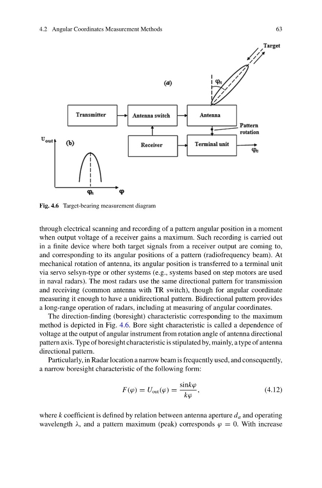
Fig. 4.6 Target-bearing measurement diagram
through electrical scanning and recording of a pattern angular position in a moment
when output voltage of a receiver gains a maximum. Such recording is carried out
in a finite device where both target signals from a receiver output are coming to,
and corresponding to its angular positions of a pattern (radiofrequency beam). At
mechanical rotation of antenna, its angular position is transferred to a terminal unit
via servo selsyn-type or other systems (e.g., systems based on step motors are used
in naval radars). The most radars use the same directional pattern for transmission
and receiving (common antenna with TR switch), though for angular coordinate
measuring it enough to have a unidirectional pattern. Bidirectional pattern provides
a long-range operation of radars, including at measuring of angular coordinates.
The direction-finding (boresight) characteristic corresponding to the maximum
method is depicted in Fig. 4.6. Bore sight characteristic is called a dependence of
voltage at the output of angular instrument from rotation angle of antenna directional
pattern axis. Type of boresight characteristic is stipulated by, mainly, a type of antenna
directional pattern.
Particularly, in Radar location a narrow beam is frequently used, and consequently,
a narrow boresight characteristic of the following form:
F(ϕ) = U out (ϕ) =
sinkϕ
kϕ
,
(4.12)
where k coefficient is defined by relation between antenna aperture d a and operating
wavelength λ, and a pattern maximum (peak) corresponds ϕ = 0. With increase
63
Fig. 4.6 Target-bearing measurement diagram
through electrical scanning and recording of a pattern angular position in a moment
when output voltage of a receiver gains a maximum. Such recording is carried out
in a finite device where both target signals from a receiver output are coming to,
and corresponding to its angular positions of a pattern (radiofrequency beam). At
mechanical rotation of antenna, its angular position is transferred to a terminal unit
via servo selsyn-type or other systems (e.g., systems based on step motors are used
in naval radars). The most radars use the same directional pattern for transmission
and receiving (common antenna with TR switch), though for angular coordinate
measuring it enough to have a unidirectional pattern. Bidirectional pattern provides
a long-range operation of radars, including at measuring of angular coordinates.
The direction-finding (boresight) characteristic corresponding to the maximum
method is depicted in Fig. 4.6. Bore sight characteristic is called a dependence of
voltage at the output of angular instrument from rotation angle of antenna directional
pattern axis. Type of boresight characteristic is stipulated by, mainly, a type of antenna
directional pattern.
Particularly, in Radar location a narrow beam is frequently used, and consequently,
a narrow boresight characteristic of the following form:
F(ϕ) = U out (ϕ) =
sinkϕ
kϕ
,
(4.12)
where k coefficient is defined by relation between antenna aperture d a and operating
wavelength λ, and a pattern maximum (peak) corresponds ϕ = 0. With increase