

50
3 Radar Targets and Its Reflecting Properties
λ/16 sin ϕ, the surface can be examined as a smooth. At extremely small gliding
angles ϕ, any surface will be as this one. For example, at λ = 3 cm and ϕ = 30
◦
,
the maximum admittable height of irregularities will be 0.75 cm, and at ϕ = 1
◦ , we
have 21.5 cm.
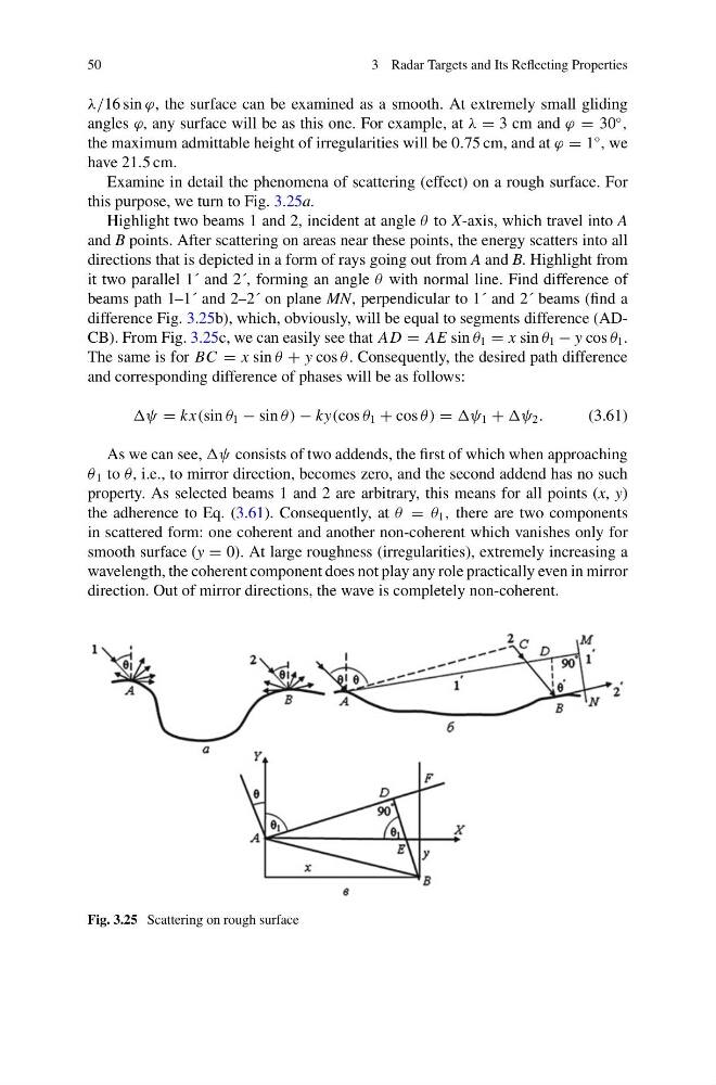
Examine in detail the phenomena of scattering (effect) on a rough surface. For
this purpose, we turn to Fig. 3.25a.
Highlight two beams 1 and 2, incident at angle θ to X-axis, which travel into A
and B points. After scattering on areas near these points, the energy scatters into all
directions that is depicted in a form of rays going out from A and B. Highlight from
it two parallel 1´ and 2´, forming an angle θ with normal line. Find difference of
beams path 1–1´ and 2–2´ on plane MN, perpendicular to 1´ and 2´ beams (find a
difference Fig. 3.25b), which, obviously, will be equal to segments difference (ADCB). From Fig. 3.25c, we can easily see that AD = AE sin θ 1 = x sin θ 1 − y cos θ 1 .
The same is for BC = x sin θ + y cos θ . Consequently, the desired path difference
and corresponding difference of phases will be as follows:
ψ = kx(sin θ 1 − sin θ ) − ky(cos θ 1 + cos θ ) = ψ 1 + ψ 2 .
(3.61)
As we can see, ψ consists of two addends, the first of which when approaching
θ 1 to θ, i.e., to mirror direction, becomes zero, and the second addend has no such
property. As selected beams 1 and 2 are arbitrary, this means for all points (x, y)
the adherence to Eq. (3.61). Consequently, at θ = θ 1 , there are two components
in scattered form: one coherent and another non-coherent which vanishes only for
smooth surface (y = 0). At large roughness (irregularities), extremely increasing a
wavelength, the coherent component does not play any role practically even in mirror
direction. Out of mirror directions, the wave is completely non-coherent.
Fig. 3.25 Scattering on rough surface
3 Radar Targets and Its Reflecting Properties
λ/16 sin ϕ, the surface can be examined as a smooth. At extremely small gliding
angles ϕ, any surface will be as this one. For example, at λ = 3 cm and ϕ = 30
◦
,
the maximum admittable height of irregularities will be 0.75 cm, and at ϕ = 1
◦ , we
have 21.5 cm.
Examine in detail the phenomena of scattering (effect) on a rough surface. For
this purpose, we turn to Fig. 3.25a.
Highlight two beams 1 and 2, incident at angle θ to X-axis, which travel into A
and B points. After scattering on areas near these points, the energy scatters into all
directions that is depicted in a form of rays going out from A and B. Highlight from
it two parallel 1´ and 2´, forming an angle θ with normal line. Find difference of
beams path 1–1´ and 2–2´ on plane MN, perpendicular to 1´ and 2´ beams (find a
difference Fig. 3.25b), which, obviously, will be equal to segments difference (ADCB). From Fig. 3.25c, we can easily see that AD = AE sin θ 1 = x sin θ 1 − y cos θ 1 .
The same is for BC = x sin θ + y cos θ . Consequently, the desired path difference
and corresponding difference of phases will be as follows:
ψ = kx(sin θ 1 − sin θ ) − ky(cos θ 1 + cos θ ) = ψ 1 + ψ 2 .
(3.61)
As we can see, ψ consists of two addends, the first of which when approaching
θ 1 to θ, i.e., to mirror direction, becomes zero, and the second addend has no such
property. As selected beams 1 and 2 are arbitrary, this means for all points (x, y)
the adherence to Eq. (3.61). Consequently, at θ = θ 1 , there are two components
in scattered form: one coherent and another non-coherent which vanishes only for
smooth surface (y = 0). At large roughness (irregularities), extremely increasing a
wavelength, the coherent component does not play any role practically even in mirror
direction. Out of mirror directions, the wave is completely non-coherent.
Fig. 3.25 Scattering on rough surface