

46
3 Radar Targets and Its Reflecting Properties
A ± σ = A 0
N ±
√
N (N − 1)
. With N = 2, this interval comprises (0.59–3.4) A 0 ,
and for N = 3 − (0.55–5.45)A 0 correspondingly.
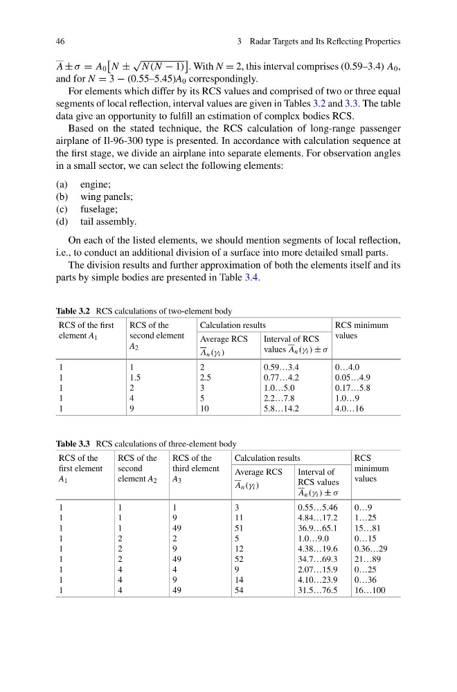
For elements which differ by its RCS values and comprised of two or three equal
segments of local reflection, interval values are given in Tables 3.2 and 3.3. The table
data give an opportunity to fulfill an estimation of complex bodies RCS.
Based on the stated technique, the RCS calculation of long-range passenger
airplane of Il-96-300 type is presented. In accordance with calculation sequence at
the first stage, we divide an airplane into separate elements. For observation angles
in a small sector, we can select the following elements:
(a) engine;
(b) wing panels;
(c) fuselage;
(d) tail assembly.
On each of the listed elements, we should mention segments of local reflection,
i.e., to conduct an additional division of a surface into more detailed small parts.
The division results and further approximation of both the elements itself and its
parts by simple bodies are presented in Table 3.4.
Table 3.2 RCS calculations of two-element body
RCS of the first
element A 1
RCS of the
second element
A 2
Calculation results
RCS minimum
values
Average RCS
A n (γ i )
Interval of RCS
values A n (γ i ) ± σ
1
1
1
1
1
1
1.5
2
4
9
2
2.5
3
5
10
0.59…3.4
0.77…4.2
1.0…5.0
2.2…7.8
5.8…14.2
0…4.0
0.05…4.9
0.17…5.8
1.0…9
4.0…16
Table 3.3 RCS calculations of three-element body
RCS of the
first element
A 1
RCS of the
second
element A 2
RCS of the
third element
A 3
Calculation results
RCS
minimum
values
Average RCS
A n (γ i )
Interval of
RCS values
A n (γ i ) ± σ
1
1
1
1
1
1
1
1
1
1
1
1
2
2
2
4
4
4
1
9
49
2
9
49
4
9
49
3
11
51
5
12
52
9
14
54
0.55…5.46
4.84…17.2
36.9…65.1
1.0…9.0
4.38…19.6
34.7…69.3
2.07…15.9
4.10…23.9
31.5…76.5
0…9
1…25
15…81
0…15
0.36…29
21…89
0…25
0…36
16…100
3 Radar Targets and Its Reflecting Properties
A ± σ = A 0
N ±
√
N (N − 1)
. With N = 2, this interval comprises (0.59–3.4) A 0 ,
and for N = 3 − (0.55–5.45)A 0 correspondingly.
For elements which differ by its RCS values and comprised of two or three equal
segments of local reflection, interval values are given in Tables 3.2 and 3.3. The table
data give an opportunity to fulfill an estimation of complex bodies RCS.
Based on the stated technique, the RCS calculation of long-range passenger
airplane of Il-96-300 type is presented. In accordance with calculation sequence at
the first stage, we divide an airplane into separate elements. For observation angles
in a small sector, we can select the following elements:
(a) engine;
(b) wing panels;
(c) fuselage;
(d) tail assembly.
On each of the listed elements, we should mention segments of local reflection,
i.e., to conduct an additional division of a surface into more detailed small parts.
The division results and further approximation of both the elements itself and its
parts by simple bodies are presented in Table 3.4.
Table 3.2 RCS calculations of two-element body
RCS of the first
element A 1
RCS of the
second element
A 2
Calculation results
RCS minimum
values
Average RCS
A n (γ i )
Interval of RCS
values A n (γ i ) ± σ
1
1
1
1
1
1
1.5
2
4
9
2
2.5
3
5
10
0.59…3.4
0.77…4.2
1.0…5.0
2.2…7.8
5.8…14.2
0…4.0
0.05…4.9
0.17…5.8
1.0…9
4.0…16
Table 3.3 RCS calculations of three-element body
RCS of the
first element
A 1
RCS of the
second
element A 2
RCS of the
third element
A 3
Calculation results
RCS
minimum
values
Average RCS
A n (γ i )
Interval of
RCS values
A n (γ i ) ± σ
1
1
1
1
1
1
1
1
1
1
1
1
2
2
2
4
4
4
1
9
49
2
9
49
4
9
49
3
11
51
5
12
52
9
14
54
0.55…5.46
4.84…17.2
36.9…65.1
1.0…9.0
4.38…19.6
34.7…69.3
2.07…15.9
4.10…23.9
31.5…76.5
0…9
1…25
15…81
0…15
0.36…29
21…89
0…25
0…36
16…100