

28
3 Radar Targets and Its Reflecting Properties
f =
rad SG
4π D 2 .
(3.20)
Generalize obtained results for the case when f vector forms some θ and γ 0
angles with Z and X coordinate system axis connected with a target. In this case, the
current phase induced in point A will be left from corresponding current phase in
point O at ψ = k AG = kr sin θ 0 value, where r = O A.
If coefficients of point A designate through (x, y), then:
ψ = kr sin θ 0 cos(γ − γ 0 ) = kr(x cos γ 0 + y sin γ 0 ) sin θ 0 .
(3.21)
As for current amplitude, then within examined assumptions, it should be considered as uniform along the whole surface of a target. A field in neighborhood of
receiving antenna will represent a sum of elementary fields created by elementary
currents flowing on target surface; herewith, a phase of elementary field will equal
2ψ.
In this case, (3.20) formula will still be correct, but G should means that as it is
admitted in antenna techniques, the product of maximum value of directional gain
G max by normalized directional pattern (in power) of antenna, which has a uniform
distribution of amplitude currents and its phases distribution according to (3.21) law,
herewith a flat aperture of such antenna coincides with a target surface.
G max value will be determined by (3.19) formula, and normalized directional
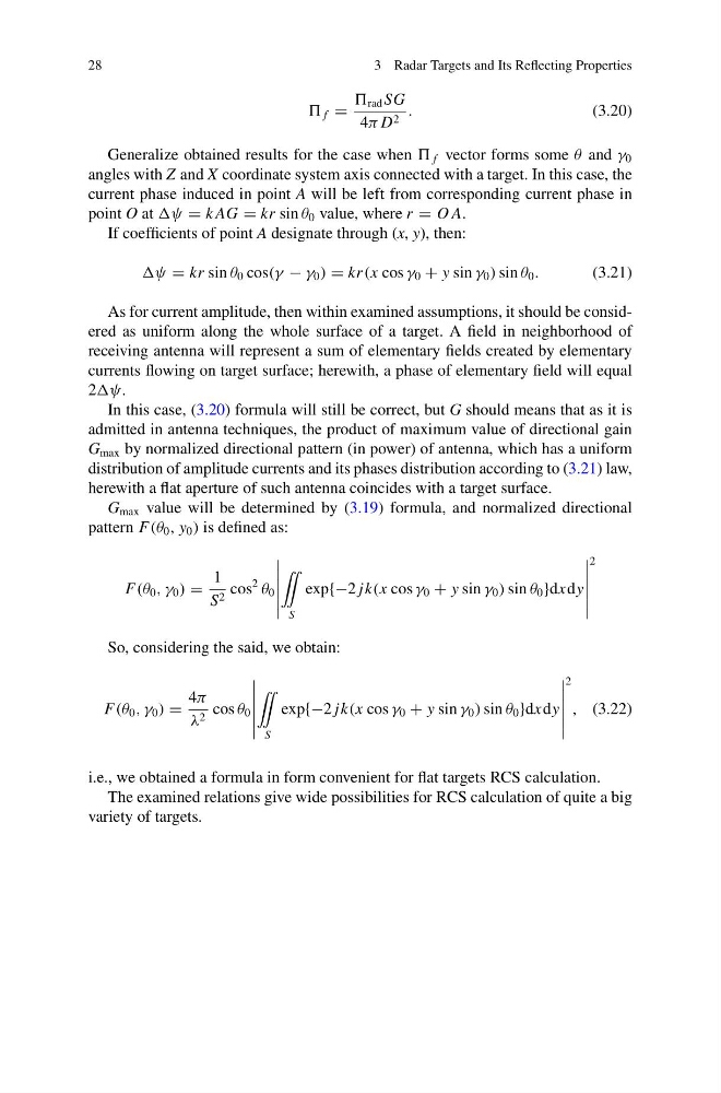
pattern F(θ 0 , y 0 ) is defined as:
F(θ 0 , γ 0 ) =
1
S 2 cos
2
θ 0
¨
S
exp{−2 jk(x cos γ 0 + y sin γ 0 ) sin θ 0 }dxdy
2
So, considering the said, we obtain:
F(θ 0 , γ 0 ) =
4π
λ 2 cos θ 0
¨
S
exp{−2 jk(x cos γ 0 + y sin γ 0 ) sin θ 0 }dxdy
2
, (3.22)
i.e., we obtained a formula in form convenient for flat targets RCS calculation.
The examined relations give wide possibilities for RCS calculation of quite a big
variety of targets.
3 Radar Targets and Its Reflecting Properties
f =
rad SG
4π D 2 .
(3.20)
Generalize obtained results for the case when f vector forms some θ and γ 0
angles with Z and X coordinate system axis connected with a target. In this case, the
current phase induced in point A will be left from corresponding current phase in
point O at ψ = k AG = kr sin θ 0 value, where r = O A.
If coefficients of point A designate through (x, y), then:
ψ = kr sin θ 0 cos(γ − γ 0 ) = kr(x cos γ 0 + y sin γ 0 ) sin θ 0 .
(3.21)
As for current amplitude, then within examined assumptions, it should be considered as uniform along the whole surface of a target. A field in neighborhood of
receiving antenna will represent a sum of elementary fields created by elementary
currents flowing on target surface; herewith, a phase of elementary field will equal
2ψ.
In this case, (3.20) formula will still be correct, but G should means that as it is
admitted in antenna techniques, the product of maximum value of directional gain
G max by normalized directional pattern (in power) of antenna, which has a uniform
distribution of amplitude currents and its phases distribution according to (3.21) law,
herewith a flat aperture of such antenna coincides with a target surface.
G max value will be determined by (3.19) formula, and normalized directional
pattern F(θ 0 , y 0 ) is defined as:
F(θ 0 , γ 0 ) =
1
S 2 cos
2
θ 0
¨
S
exp{−2 jk(x cos γ 0 + y sin γ 0 ) sin θ 0 }dxdy
2
So, considering the said, we obtain:
F(θ 0 , γ 0 ) =
4π
λ 2 cos θ 0
¨
S
exp{−2 jk(x cos γ 0 + y sin γ 0 ) sin θ 0 }dxdy
2
, (3.22)
i.e., we obtained a formula in form convenient for flat targets RCS calculation.
The examined relations give wide possibilities for RCS calculation of quite a big
variety of targets.