

3.2 Radar Cross Section of Radar Targets
23
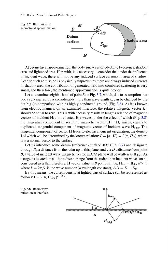
Fig. 3.7 Illustration of
geometrical approximation
At geometrical approximation, the body surface is divided into two zones: shadow
area and lightened area. Herewith, it is necessary to consider that under the influence
of incident wave, there will not be any induced surface currents in area of shadow.
Despite such admission is physically unproven as there are always induced currents
in shadow area, the contribution of generated field into combined scattering is very
small, and therefore, the mentioned approximation is quite proper.
Let us examine neighborhood of point B on Fig. 3.7, which, due to assumption that
body curving radius is considerably more than wavelength λ, can be changed by the
flat big (in comparison with λ) highly conducted ground (Fig. 3.8). As it is known
from electrodynamics, on an examined interface, the relative magnetic vector ˙
H n
should be equal to zero. This is with necessity results in lengths relation of magnetic
vectors of incident H inc to reflected H rfl waves, under the effect of which (Fig. 3.8)
the tangential component of resulting magnetic vector H = H τ arises, equals to
duplicated tangential component of magnetic vector of incident wave H τ inc . The
tangential component of vector H leads to electrical current origination, the density
I of which will be determined by the known relation: I = [n, H] = 2[n, H τ ], where
n is a normal vector to the surface.
Let us introduce some datum (reference) surface MM (Fig. 3.7) and designate
through D 0 a distance from the radar up to this plane, and via D a distance from point
B; a value of incident wave magnetic vector in MM plane will be written as H 0inc . As
a target is located on a quite a distant range from the radar, then incident wave can be
considered as a flat; therefore, H vector value in B point will be: H inc = H 0inc e
− jkr ,
where k = 2π/λ is the wave number (wavelength constant), D = D − D 0 .
By this means, the current density at lighted part of surface can be represented as
follows: I = 2[n, H 0inc ]e
− jk R .
Fig. 3.8 Radio wave
reflection at interface
23
Fig. 3.7 Illustration of
geometrical approximation
At geometrical approximation, the body surface is divided into two zones: shadow
area and lightened area. Herewith, it is necessary to consider that under the influence
of incident wave, there will not be any induced surface currents in area of shadow.
Despite such admission is physically unproven as there are always induced currents
in shadow area, the contribution of generated field into combined scattering is very
small, and therefore, the mentioned approximation is quite proper.
Let us examine neighborhood of point B on Fig. 3.7, which, due to assumption that
body curving radius is considerably more than wavelength λ, can be changed by the
flat big (in comparison with λ) highly conducted ground (Fig. 3.8). As it is known
from electrodynamics, on an examined interface, the relative magnetic vector ˙
H n
should be equal to zero. This is with necessity results in lengths relation of magnetic
vectors of incident H inc to reflected H rfl waves, under the effect of which (Fig. 3.8)
the tangential component of resulting magnetic vector H = H τ arises, equals to
duplicated tangential component of magnetic vector of incident wave H τ inc . The
tangential component of vector H leads to electrical current origination, the density
I of which will be determined by the known relation: I = [n, H] = 2[n, H τ ], where
n is a normal vector to the surface.
Let us introduce some datum (reference) surface MM (Fig. 3.7) and designate
through D 0 a distance from the radar up to this plane, and via D a distance from point
B; a value of incident wave magnetic vector in MM plane will be written as H 0inc . As
a target is located on a quite a distant range from the radar, then incident wave can be
considered as a flat; therefore, H vector value in B point will be: H inc = H 0inc e
− jkr ,
where k = 2π/λ is the wave number (wavelength constant), D = D − D 0 .
By this means, the current density at lighted part of surface can be represented as
follows: I = 2[n, H 0inc ]e
− jk R .
Fig. 3.8 Radio wave
reflection at interface