

17 Radio-Navigational Speed and Drift Angle Meters
321
f Dl =
2
λ 0
W x l x + W y l y + W z l z
,
(17.3)
f Dm =
2
λ 0
W x m x + W y m y + W z m z
,
(17.4)
f Dn =
2
λ 0
W x n x + W y n y + W z n z
.
(17.5)
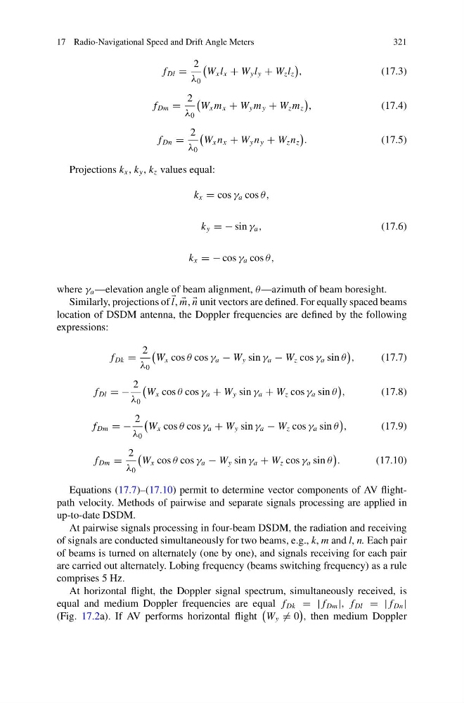
Projections k x , k y , k z values equal:
k x = cos γ a cos θ,
k y = − sin γ a ,
(17.6)
k x = − cos γ a cos θ,
where γ a —elevation angle of beam alignment, θ —azimuth of beam boresight.
Similarly, projections of
l,
m,
n unit vectors are defined. For equally spaced beams
location of DSDM antenna, the Doppler frequencies are defined by the following
expressions:
f Dk =
2
λ 0
W x cos θ cos γ a − W y sin γ a − W z cos γ a sin θ
,
(17.7)
f Dl = −
2
λ 0
W x cos θ cos γ a + W y sin γ a + W z cos γ a sin θ
,
(17.8)
f Dm = −
2
λ 0
W x cos θ cos γ a + W y sin γ a − W z cos γ a sin θ
,
(17.9)
f Dm =
2
λ 0
W x cos θ cos γ a − W y sin γ a + W z cos γ a sin θ
.
(17.10)
Equations (17.7)–(17.10) permit to determine vector components of AV flightpath velocity. Methods of pairwise and separate signals processing are applied in
up-to-date DSDM.
At pairwise signals processing in four-beam DSDM, the radiation and receiving
of signals are conducted simultaneously for two beams, e.g., k, m and l, n. Each pair
of beams is turned on alternately (one by one), and signals receiving for each pair
are carried out alternately. Lobing frequency (beams switching frequency) as a rule
comprises 5 Hz.
At horizontal flight, the Doppler signal spectrum, simultaneously received, is
equal and medium Doppler frequencies are equal f Dk = | f Dm |, f Dl = | f Dn |
(Fig. 17.2a). If AV performs horizontal flight
W y = 0
, then medium Doppler
321
f Dl =
2
λ 0
W x l x + W y l y + W z l z
,
(17.3)
f Dm =
2
λ 0
W x m x + W y m y + W z m z
,
(17.4)
f Dn =
2
λ 0
W x n x + W y n y + W z n z
.
(17.5)
Projections k x , k y , k z values equal:
k x = cos γ a cos θ,
k y = − sin γ a ,
(17.6)
k x = − cos γ a cos θ,
where γ a —elevation angle of beam alignment, θ —azimuth of beam boresight.
Similarly, projections of
l,
m,
n unit vectors are defined. For equally spaced beams
location of DSDM antenna, the Doppler frequencies are defined by the following
expressions:
f Dk =
2
λ 0
W x cos θ cos γ a − W y sin γ a − W z cos γ a sin θ
,
(17.7)
f Dl = −
2
λ 0
W x cos θ cos γ a + W y sin γ a + W z cos γ a sin θ
,
(17.8)
f Dm = −
2
λ 0
W x cos θ cos γ a + W y sin γ a − W z cos γ a sin θ
,
(17.9)
f Dm =
2
λ 0
W x cos θ cos γ a − W y sin γ a + W z cos γ a sin θ
.
(17.10)
Equations (17.7)–(17.10) permit to determine vector components of AV flightpath velocity. Methods of pairwise and separate signals processing are applied in
up-to-date DSDM.
At pairwise signals processing in four-beam DSDM, the radiation and receiving
of signals are conducted simultaneously for two beams, e.g., k, m and l, n. Each pair
of beams is turned on alternately (one by one), and signals receiving for each pair
are carried out alternately. Lobing frequency (beams switching frequency) as a rule
comprises 5 Hz.
At horizontal flight, the Doppler signal spectrum, simultaneously received, is
equal and medium Doppler frequencies are equal f Dk = | f Dm |, f Dl = | f Dn |
(Fig. 17.2a). If AV performs horizontal flight
W y = 0
, then medium Doppler