

15.2 Radio Direction-Finding Goniometric Radio Navigation Systems
309
Additional measuring error of HA, stipulated by this effect, can be 5°. Minimal
aircraft altitude (height) H min , at which this error is minimum or even is missing.
H min ≥
900,000
f L
(15.37)
where f L —LB operating frequency.
This error also decreases at LB bearing, located as close as possible to
perpendicular line from aircraft to medium coastal line.
Polarization error. Mid-band radio waves can propagate along ground surface
by enveloping it, and also (especially at night time) via reflection from ionosphere. At
reflection from ionosphere, an electromagnetic field effects on a frame antenna, the
direction vector of which comprises some angle with horizontal plane. Horizontal
component of this vector induces in horizontal arms of a frame. As a result, an
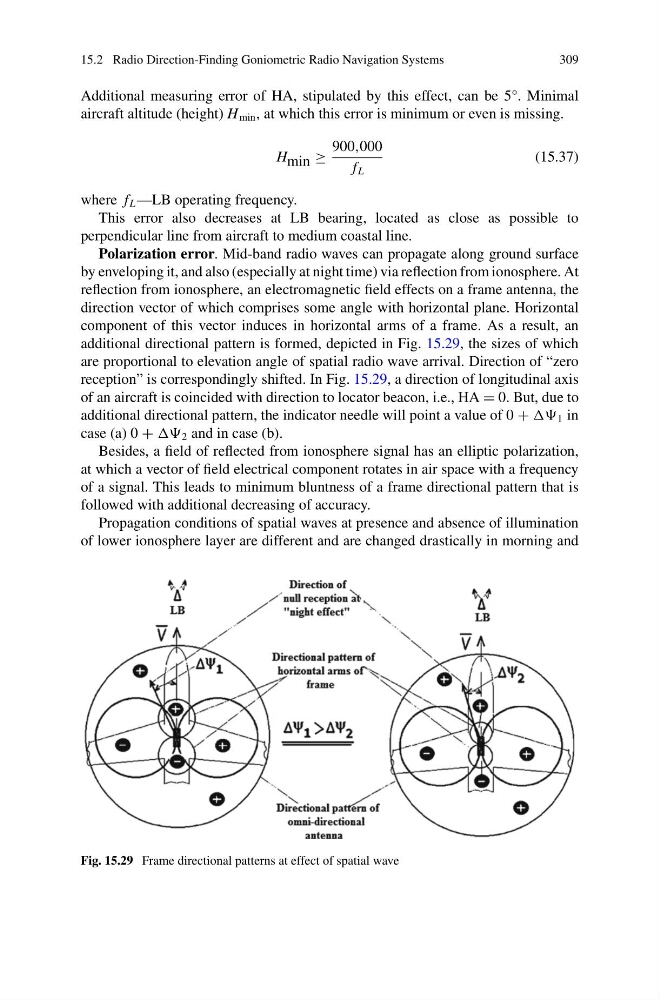
additional directional pattern is formed, depicted in Fig. 15.29, the sizes of which
are proportional to elevation angle of spatial radio wave arrival. Direction of “zero
reception” is correspondingly shifted. In Fig. 15.29, a direction of longitudinal axis
of an aircraft is coincided with direction to locator beacon, i.e., HA = 0. But, due to
additional directional pattern, the indicator needle will point a value of 0 + 1 in
case (a) 0 + 2 and in case (b).
Besides, a field of reflected from ionosphere signal has an elliptic polarization,
at which a vector of field electrical component rotates in air space with a frequency
of a signal. This leads to minimum bluntness of a frame directional pattern that is
followed with additional decreasing of accuracy.
Propagation conditions of spatial waves at presence and absence of illumination
of lower ionosphere layer are different and are changed drastically in morning and
Fig. 15.29 Frame directional patterns at effect of spatial wave
309
Additional measuring error of HA, stipulated by this effect, can be 5°. Minimal
aircraft altitude (height) H min , at which this error is minimum or even is missing.
H min ≥
900,000
f L
(15.37)
where f L —LB operating frequency.
This error also decreases at LB bearing, located as close as possible to
perpendicular line from aircraft to medium coastal line.
Polarization error. Mid-band radio waves can propagate along ground surface
by enveloping it, and also (especially at night time) via reflection from ionosphere. At
reflection from ionosphere, an electromagnetic field effects on a frame antenna, the
direction vector of which comprises some angle with horizontal plane. Horizontal
component of this vector induces in horizontal arms of a frame. As a result, an
additional directional pattern is formed, depicted in Fig. 15.29, the sizes of which
are proportional to elevation angle of spatial radio wave arrival. Direction of “zero
reception” is correspondingly shifted. In Fig. 15.29, a direction of longitudinal axis
of an aircraft is coincided with direction to locator beacon, i.e., HA = 0. But, due to
additional directional pattern, the indicator needle will point a value of 0 + 1 in
case (a) 0 + 2 and in case (b).
Besides, a field of reflected from ionosphere signal has an elliptic polarization,
at which a vector of field electrical component rotates in air space with a frequency
of a signal. This leads to minimum bluntness of a frame directional pattern that is
followed with additional decreasing of accuracy.
Propagation conditions of spatial waves at presence and absence of illumination
of lower ionosphere layer are different and are changed drastically in morning and
Fig. 15.29 Frame directional patterns at effect of spatial wave