

288
15 Goniometric Radio Navigation Systems
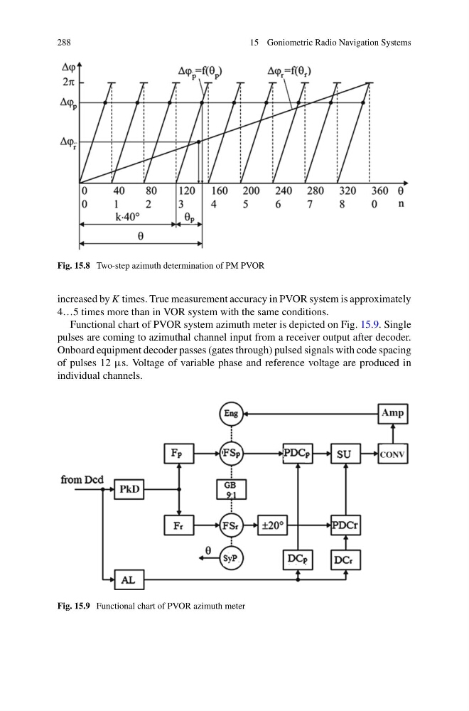
Fig. 15.8 Two-step azimuth determination of PM PVOR
increased by K times. True measurement accuracy in PVOR system is approximately
4…5 times more than in VOR system with the same conditions.
Functional chart of PVOR system azimuth meter is depicted on Fig. 15.9. Single
pulses are coming to azimuthal channel input from a receiver output after decoder.
Onboard equipment decoder passes (gates through) pulsed signals with code spacing
of pulses 12 μs. Voltage of variable phase and reference voltage are produced in
individual channels.
Fig. 15.9 Functional chart of PVOR azimuth meter
15 Goniometric Radio Navigation Systems
Fig. 15.8 Two-step azimuth determination of PM PVOR
increased by K times. True measurement accuracy in PVOR system is approximately
4…5 times more than in VOR system with the same conditions.
Functional chart of PVOR system azimuth meter is depicted on Fig. 15.9. Single
pulses are coming to azimuthal channel input from a receiver output after decoder.
Onboard equipment decoder passes (gates through) pulsed signals with code spacing
of pulses 12 μs. Voltage of variable phase and reference voltage are produced in
individual channels.
Fig. 15.9 Functional chart of PVOR azimuth meter