

9 Compensation of Signals from Stationary Objects
169
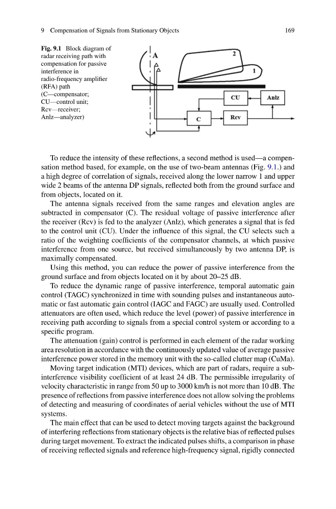
Fig. 9.1 Block diagram of
radar receiving path with
compensation for passive
interference in
radio-frequency amplifier
(RFA) path
(C—compensator;
CU—control unit;
Rcv—receiver;
Anlz—analyzer)
To reduce the intensity of these reflections, a second method is used—a compensation method based, for example, on the use of two-beam antennas (Fig. 9.1.) and
a high degree of correlation of signals, received along the lower narrow 1 and upper
wide 2 beams of the antenna DP signals, reflected both from the ground surface and
from objects, located on it.
The antenna signals received from the same ranges and elevation angles are
subtracted in compensator (C). The residual voltage of passive interference after
the receiver (Rcv) is fed to the analyzer (Anlz), which generates a signal that is fed
to the control unit (CU). Under the influence of this signal, the CU selects such a
ratio of the weighting coefficients of the compensator channels, at which passive
interference from one source, but received simultaneously by two antenna DP, is
maximally compensated.
Using this method, you can reduce the power of passive interference from the
ground surface and from objects located on it by about 20–25 dB.
To reduce the dynamic range of passive interference, temporal automatic gain
control (TAGC) synchronized in time with sounding pulses and instantaneous automatic or fast automatic gain control (IAGC and FAGC) are usually used. Controlled
attenuators are often used, which reduce the level (power) of passive interference in
receiving path according to signals from a special control system or according to a
specific program.
The attenuation (gain) control is performed in each element of the radar working
area resolution in accordance with the continuously updated value of average passive
interference power stored in the memory unit with the so-called clutter map (CuMa).
Moving target indication (MTI) devices, which are part of radars, require a subinterference visibility coefficient of at least 24 dB. The permissible irregularity of
velocity characteristic in range from 50 up to 3000 km/h is not more than 10 dB. The
presence of reflections from passive interference does not allow solving the problems
of detecting and measuring of coordinates of aerial vehicles without the use of MTI
systems.
The main effect that can be used to detect moving targets against the background
of interfering reflections from stationary objects is the relative bias of reflected pulses
during target movement. To extract the indicated pulses shifts, a comparison in phase
of receiving reflected signals and reference high-frequency signal, rigidly connected
169
Fig. 9.1 Block diagram of
radar receiving path with
compensation for passive
interference in
radio-frequency amplifier
(RFA) path
(C—compensator;
CU—control unit;
Rcv—receiver;
Anlz—analyzer)
To reduce the intensity of these reflections, a second method is used—a compensation method based, for example, on the use of two-beam antennas (Fig. 9.1.) and
a high degree of correlation of signals, received along the lower narrow 1 and upper
wide 2 beams of the antenna DP signals, reflected both from the ground surface and
from objects, located on it.
The antenna signals received from the same ranges and elevation angles are
subtracted in compensator (C). The residual voltage of passive interference after
the receiver (Rcv) is fed to the analyzer (Anlz), which generates a signal that is fed
to the control unit (CU). Under the influence of this signal, the CU selects such a
ratio of the weighting coefficients of the compensator channels, at which passive
interference from one source, but received simultaneously by two antenna DP, is
maximally compensated.
Using this method, you can reduce the power of passive interference from the
ground surface and from objects located on it by about 20–25 dB.
To reduce the dynamic range of passive interference, temporal automatic gain
control (TAGC) synchronized in time with sounding pulses and instantaneous automatic or fast automatic gain control (IAGC and FAGC) are usually used. Controlled
attenuators are often used, which reduce the level (power) of passive interference in
receiving path according to signals from a special control system or according to a
specific program.
The attenuation (gain) control is performed in each element of the radar working
area resolution in accordance with the continuously updated value of average passive
interference power stored in the memory unit with the so-called clutter map (CuMa).
Moving target indication (MTI) devices, which are part of radars, require a subinterference visibility coefficient of at least 24 dB. The permissible irregularity of
velocity characteristic in range from 50 up to 3000 km/h is not more than 10 dB. The
presence of reflections from passive interference does not allow solving the problems
of detecting and measuring of coordinates of aerial vehicles without the use of MTI
systems.
The main effect that can be used to detect moving targets against the background
of interfering reflections from stationary objects is the relative bias of reflected pulses
during target movement. To extract the indicated pulses shifts, a comparison in phase
of receiving reflected signals and reference high-frequency signal, rigidly connected