

150
7 Non-coherent and Pseudo-coherent Radar Systems
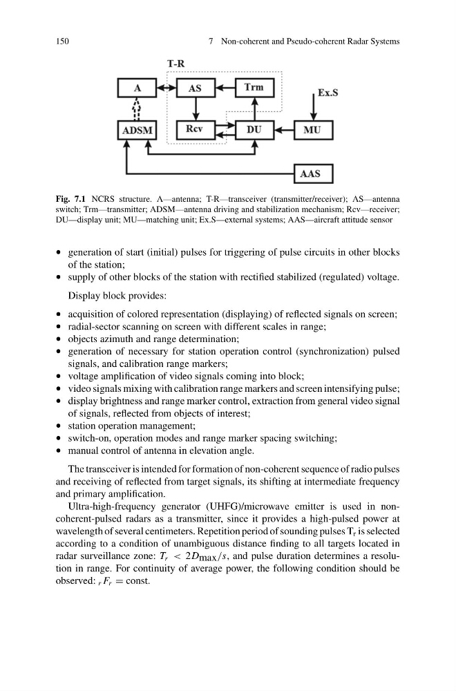
Fig. 7.1 NCRS structure. A—antenna; T-R—transceiver (transmitter/receiver); AS—antenna
switch; Trm—transmitter; ADSM—antenna driving and stabilization mechanism; Rcv—receiver;
DU—display unit; MU—matching unit; Ex.S—external systems; AAS—aircraft attitude sensor
• generation of start (initial) pulses for triggering of pulse circuits in other blocks
of the station;
• supply of other blocks of the station with rectified stabilized (regulated) voltage.
Display block provides:
• acquisition of colored representation (displaying) of reflected signals on screen;
• radial-sector scanning on screen with different scales in range;
• objects azimuth and range determination;
• generation of necessary for station operation control (synchronization) pulsed
signals, and calibration range markers;
• voltage amplification of video signals coming into block;
• video signals mixing with calibration range markers and screen intensifying pulse;
• display brightness and range marker control, extraction from general video signal
of signals, reflected from objects of interest;
• station operation management;
• switch-on, operation modes and range marker spacing switching;
• manual control of antenna in elevation angle.
The transceiver is intended for formation of non-coherent sequence of radio pulses
and receiving of reflected from target signals, its shifting at intermediate frequency
and primary amplification.
Ultra-high-frequency generator (UHFG)/microwave emitter is used in noncoherent-pulsed radars as a transmitter, since it provides a high-pulsed power at
wavelength of several centimeters. Repetition period of sounding pulses T r is selected
according to a condition of unambiguous distance finding to all targets located in
radar surveillance zone: T r < 2D max /s, and pulse duration determines a resolution in range. For continuity of average power, the following condition should be
observed: r F r = const.
7 Non-coherent and Pseudo-coherent Radar Systems
Fig. 7.1 NCRS structure. A—antenna; T-R—transceiver (transmitter/receiver); AS—antenna
switch; Trm—transmitter; ADSM—antenna driving and stabilization mechanism; Rcv—receiver;
DU—display unit; MU—matching unit; Ex.S—external systems; AAS—aircraft attitude sensor
• generation of start (initial) pulses for triggering of pulse circuits in other blocks
of the station;
• supply of other blocks of the station with rectified stabilized (regulated) voltage.
Display block provides:
• acquisition of colored representation (displaying) of reflected signals on screen;
• radial-sector scanning on screen with different scales in range;
• objects azimuth and range determination;
• generation of necessary for station operation control (synchronization) pulsed
signals, and calibration range markers;
• voltage amplification of video signals coming into block;
• video signals mixing with calibration range markers and screen intensifying pulse;
• display brightness and range marker control, extraction from general video signal
of signals, reflected from objects of interest;
• station operation management;
• switch-on, operation modes and range marker spacing switching;
• manual control of antenna in elevation angle.
The transceiver is intended for formation of non-coherent sequence of radio pulses
and receiving of reflected from target signals, its shifting at intermediate frequency
and primary amplification.
Ultra-high-frequency generator (UHFG)/microwave emitter is used in noncoherent-pulsed radars as a transmitter, since it provides a high-pulsed power at
wavelength of several centimeters. Repetition period of sounding pulses T r is selected
according to a condition of unambiguous distance finding to all targets located in
radar surveillance zone: T r < 2D max /s, and pulse duration determines a resolution in range. For continuity of average power, the following condition should be
observed: r F r = const.