

6.2 Coordinates and Movement Parameters Measuring …
145
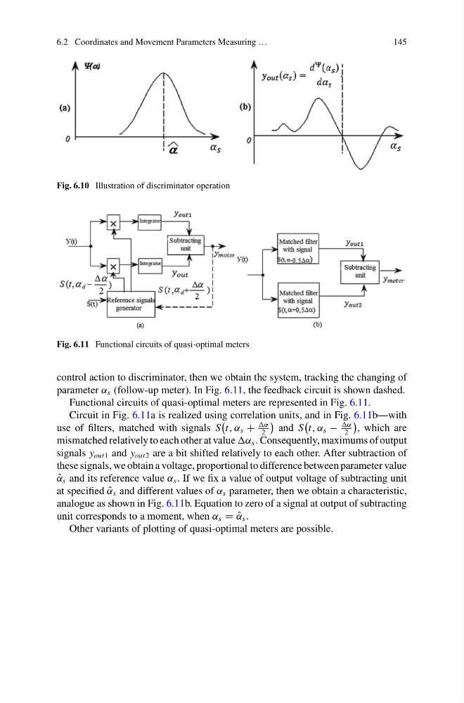
Fig. 6.10 Illustration of discriminator operation
Fig. 6.11 Functional circuits of quasi-optimal meters
control action to discriminator, then we obtain the system, tracking the changing of
parameter α s (follow-up meter). In Fig. 6.11, the feedback circuit is shown dashed.
Functional circuits of quasi-optimal meters are represented in Fig. 6.11.
Circuit in Fig. 6.11a is realized using correlation units, and in Fig. 6.11b—with
use of filters, matched with signals S
t, α s +
α
2
and S
t, α s −
α
2
, which are
mismatched relatively to each other at value α s . Consequently, maximums of output
signals y out1 and y out2 are a bit shifted relatively to each other. After subtraction of
these signals, we obtain a voltage, proportional to difference between parameter value
ˆ
α s and its reference value α s . If we fix a value of output voltage of subtracting unit
at specified ˆ
α s and different values of α s parameter, then we obtain a characteristic,
analogue as shown in Fig. 6.11b. Equation to zero of a signal at output of subtracting
unit corresponds to a moment, when α s = ˆ
α s .
Other variants of plotting of quasi-optimal meters are possible.
145
Fig. 6.10 Illustration of discriminator operation
Fig. 6.11 Functional circuits of quasi-optimal meters
control action to discriminator, then we obtain the system, tracking the changing of
parameter α s (follow-up meter). In Fig. 6.11, the feedback circuit is shown dashed.
Functional circuits of quasi-optimal meters are represented in Fig. 6.11.
Circuit in Fig. 6.11a is realized using correlation units, and in Fig. 6.11b—with
use of filters, matched with signals S
t, α s +
α
2
and S
t, α s −
α
2
, which are
mismatched relatively to each other at value α s . Consequently, maximums of output
signals y out1 and y out2 are a bit shifted relatively to each other. After subtraction of
these signals, we obtain a voltage, proportional to difference between parameter value
ˆ
α s and its reference value α s . If we fix a value of output voltage of subtracting unit
at specified ˆ
α s and different values of α s parameter, then we obtain a characteristic,
analogue as shown in Fig. 6.11b. Equation to zero of a signal at output of subtracting
unit corresponds to a moment, when α s = ˆ
α s .
Other variants of plotting of quasi-optimal meters are possible.