

138
6 Detection of Radio Signals and Its Parameters Measuring
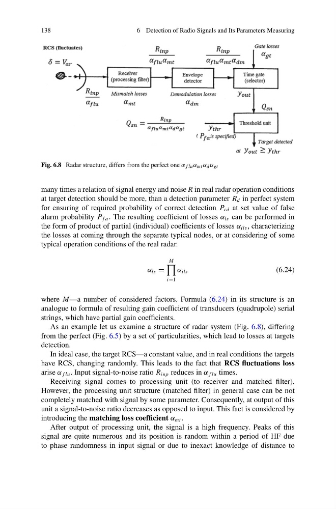
Fig. 6.8 Radar structure, differs from the perfect one α f lu α mt α d α gt
many times a relation of signal energy and noise R in real radar operation conditions
at target detection should be more, than a detection parameter R d in perfect system
for ensuring of required probability of correct detection P cd at set value of false
alarm probability P f a . The resulting coefficient of losses α ls can be performed in
the form of product of partial (individual) coefficients of losses α ils , characterizing
the losses at coming through the separate typical nodes, or at considering of some
typical operation conditions of the real radar.
α ls =
M
i=1
α ils
(6.24)
where M—a number of considered factors. Formula (6.24) in its structure is an
analogue to formula of resulting gain coefficient of transducers (quadrupole) serial
strings, which have partial gain coefficients.
As an example let us examine a structure of radar system (Fig. 6.8), differing
from the perfect (Fig. 6.5) by a set of particularities, which lead to losses at targets
detection.
In ideal case, the target RCS—a constant value, and in real conditions the targets
have RCS, changing randomly. This leads to the fact that RCS fluctuations loss
arise α f lu . Input signal-to-noise ratio R inp reduces in α f lu times.
Receiving signal comes to processing unit (to receiver and matched filter).
However, the processing unit structure (matched filter) in general case can be not
completely matched with signal by some parameter. Consequently, at output of this
unit a signal-to-noise ratio decreases as opposed to input. This fact is considered by
introducing the matching loss coefficient α mt .
After output of processing unit, the signal is a high frequency. Peaks of this
signal are quite numerous and its position is random within a period of HF due
to phase randomness in input signal or due to inexact knowledge of distance to
6 Detection of Radio Signals and Its Parameters Measuring
Fig. 6.8 Radar structure, differs from the perfect one α f lu α mt α d α gt
many times a relation of signal energy and noise R in real radar operation conditions
at target detection should be more, than a detection parameter R d in perfect system
for ensuring of required probability of correct detection P cd at set value of false
alarm probability P f a . The resulting coefficient of losses α ls can be performed in
the form of product of partial (individual) coefficients of losses α ils , characterizing
the losses at coming through the separate typical nodes, or at considering of some
typical operation conditions of the real radar.
α ls =
M
i=1
α ils
(6.24)
where M—a number of considered factors. Formula (6.24) in its structure is an
analogue to formula of resulting gain coefficient of transducers (quadrupole) serial
strings, which have partial gain coefficients.
As an example let us examine a structure of radar system (Fig. 6.8), differing
from the perfect (Fig. 6.5) by a set of particularities, which lead to losses at targets
detection.
In ideal case, the target RCS—a constant value, and in real conditions the targets
have RCS, changing randomly. This leads to the fact that RCS fluctuations loss
arise α f lu . Input signal-to-noise ratio R inp reduces in α f lu times.
Receiving signal comes to processing unit (to receiver and matched filter).
However, the processing unit structure (matched filter) in general case can be not
completely matched with signal by some parameter. Consequently, at output of this
unit a signal-to-noise ratio decreases as opposed to input. This fact is considered by
introducing the matching loss coefficient α mt .
After output of processing unit, the signal is a high frequency. Peaks of this
signal are quite numerous and its position is random within a period of HF due
to phase randomness in input signal or due to inexact knowledge of distance to