

As a result of the numerical computations the particle position at this time as a
function of the initial position of the fluid elements (denoted by the index j) is shown
in Fig. A.9 and the marker at 9.019 show the position of the particle at that time. It
can be seen from this plot that this marker corresponds to the fluid element with an
initial position (within the numerical approximations) at x ¼ 94Δx ¼ 9.4. Accordingly, the approximate particle velocity is given by u 1180, 94 , and the numerical
output gives the following result,
u 1180,94 ¼ À0:128,
which is in good agreement with the value of À0.125 according to the method of
characteristics. The particle velocity for this fluid element is shown plotted as a
function of time in Fig. A.10 and the marker at t ¼ 11.8 identifies the particle
velocity at this time as À0.128 as noted above.
Let us now consider another point P 12 in ℜ 4 with coordinates, (6.390, 13.736).
The Riemann invariants passing through this point are R + ¼ 4.75 and R À ¼ À 5.5,
hence, the particle velocity according to the equation, u ¼ (R + + R À )/2, is
u ¼ À 0.375. For this particular point we have, n ¼ 13.736/Δt ffi 1374, and a
numerically generated plot of x 1374, j versus j is shown in Fig. A.11. The marker in
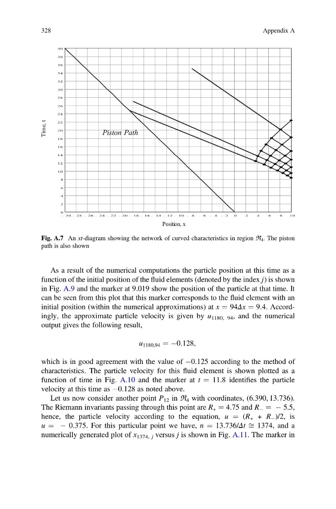
Fig. A.7 An xt-diagram showing the network of curved characteristics in region ℜ 4 . The piston
path is also shown
328
Appendix A
function of the initial position of the fluid elements (denoted by the index j) is shown
in Fig. A.9 and the marker at 9.019 show the position of the particle at that time. It
can be seen from this plot that this marker corresponds to the fluid element with an
initial position (within the numerical approximations) at x ¼ 94Δx ¼ 9.4. Accordingly, the approximate particle velocity is given by u 1180, 94 , and the numerical
output gives the following result,
u 1180,94 ¼ À0:128,
which is in good agreement with the value of À0.125 according to the method of
characteristics. The particle velocity for this fluid element is shown plotted as a
function of time in Fig. A.10 and the marker at t ¼ 11.8 identifies the particle
velocity at this time as À0.128 as noted above.
Let us now consider another point P 12 in ℜ 4 with coordinates, (6.390, 13.736).
The Riemann invariants passing through this point are R + ¼ 4.75 and R À ¼ À 5.5,
hence, the particle velocity according to the equation, u ¼ (R + + R À )/2, is
u ¼ À 0.375. For this particular point we have, n ¼ 13.736/Δt ffi 1374, and a
numerically generated plot of x 1374, j versus j is shown in Fig. A.11. The marker in
Fig. A.7 An xt-diagram showing the network of curved characteristics in region ℜ 4 . The piston
path is also shown
328
Appendix A