

Solid State Physics
287
E
B
C
p
n
p
V c
I c
I b
V b
V b
V c
(a)
(b)
p
n
p
E
B
C
R i
V i
R o
V o
I e
I c
(c)
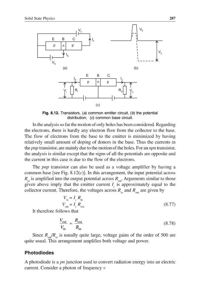
Fig. 8.12. Transistors, (a) common emitter circuit, (b) the potential
distribution, (c) common base circuit.
In the analysis so far the motion of only holes has been considered. Regarding
the electrons, there is hardly any electron flow from the collector to the base.
The flow of electrons from the base to the emitter is minimized by having
relatively small amount of doping of donors in the base. Thus the currents in
the pnp transistor, are mainly due to the motion of the holes. For an npn transistor,
the analysis is similar except that the signs of all the potentials are opposite and
the current in this case is due to the flow of the electrons.
The pnp transistor can also be used as a voltage amplifier by having a
common base [see Fig. 8.12(c)]. In this arrangement, the input potential across
R in is amplified into the output potential across R out . Arguments similar to those
given above imply that the emitter current I c is approximately equal to the
collector current. Therefore, the voltages across R in and R out are given by
V in = I c R in
V out = I c R out
(8.77)
It therefore follows that
out
in
V
V
≈
out
in
R
R
(8.78)
Since R out /R in is usually quite large, voltage gains of the order of 500 are
quite usual. This arrangement amplifies both voltage and power.
Photodiodes
A photodiode is a pn junction used to convert radiation energy into an electric
current. Consider a photon of frequency v
287
E
B
C
p
n
p
V c
I c
I b
V b
V b
V c
(a)
(b)
p
n
p
E
B
C
R i
V i
R o
V o
I e
I c
(c)
Fig. 8.12. Transistors, (a) common emitter circuit, (b) the potential
distribution, (c) common base circuit.
In the analysis so far the motion of only holes has been considered. Regarding
the electrons, there is hardly any electron flow from the collector to the base.
The flow of electrons from the base to the emitter is minimized by having
relatively small amount of doping of donors in the base. Thus the currents in
the pnp transistor, are mainly due to the motion of the holes. For an npn transistor,
the analysis is similar except that the signs of all the potentials are opposite and
the current in this case is due to the flow of the electrons.
The pnp transistor can also be used as a voltage amplifier by having a
common base [see Fig. 8.12(c)]. In this arrangement, the input potential across
R in is amplified into the output potential across R out . Arguments similar to those
given above imply that the emitter current I c is approximately equal to the
collector current. Therefore, the voltages across R in and R out are given by
V in = I c R in
V out = I c R out
(8.77)
It therefore follows that
out
in
V
V
≈
out
in
R
R
(8.78)
Since R out /R in is usually quite large, voltage gains of the order of 500 are
quite usual. This arrangement amplifies both voltage and power.
Photodiodes
A photodiode is a pn junction used to convert radiation energy into an electric
current. Consider a photon of frequency v