

Elements of Modern Physics
284
At equilibrium, there is no net flow, so that
I e (p → n) = I e (n → p) = I 0
and hence
c 1 = c 2
(8.73)
where Eq. (8.69) has been used.
If now an external potential – V is applied, the potential difference across
the boundary is V 0 – V. Since the concentrations are unchanged, the current is
I = c 2 n e (n) exp [– e (V 0 – V)/kT] – c 1 n e (p)
= I 0 [exp (eV/kT) – 1]
(8.74)
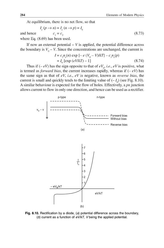
Thus if (– eV) has the sign opposite to that of eV 0 , i.e., eV is positive, what
is termed as forward bias, the current increases rapidly, whereas if (– eV) has
the same sign as that of eV, i.e., eV is negative, known as reverse bias, the
current is small and quickly tends to the limiting value of (– I 0 ) (see Fig. 8.10).
A similar behaviour is expected for the flow of holes. Effectively, a pn junction
allows current to flow in only one direction, and hence can be used as a rectifier.
p-type
n-type
v – v
a
Forward bias
Without bias
Reverse bias
(a)
7
6
5
4
3
2
1
– eV /kT
B
eV/kT
I
I o
(b)
Fig. 8.10. Rectification by a diode, (a) potential difference across the boundary,
(b) current as a function of eV/kT, V being the applied potential.
284
At equilibrium, there is no net flow, so that
I e (p → n) = I e (n → p) = I 0
and hence
c 1 = c 2
(8.73)
where Eq. (8.69) has been used.
If now an external potential – V is applied, the potential difference across
the boundary is V 0 – V. Since the concentrations are unchanged, the current is
I = c 2 n e (n) exp [– e (V 0 – V)/kT] – c 1 n e (p)
= I 0 [exp (eV/kT) – 1]
(8.74)
Thus if (– eV) has the sign opposite to that of eV 0 , i.e., eV is positive, what
is termed as forward bias, the current increases rapidly, whereas if (– eV) has
the same sign as that of eV, i.e., eV is negative, known as reverse bias, the
current is small and quickly tends to the limiting value of (– I 0 ) (see Fig. 8.10).
A similar behaviour is expected for the flow of holes. Effectively, a pn junction
allows current to flow in only one direction, and hence can be used as a rectifier.
p-type
n-type
v – v
a
Forward bias
Without bias
Reverse bias
(a)
7
6
5
4
3
2
1
– eV /kT
B
eV/kT
I
I o
(b)
Fig. 8.10. Rectification by a diode, (a) potential difference across the boundary,
(b) current as a function of eV/kT, V being the applied potential.