

Elements of Modern Physics
200
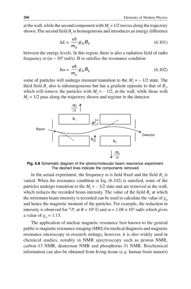
at the wall, while the second component with M I = 1/2 moves along the trajectory
shown. The second field B 2 is homogeneous and introduces an energy difference
∆E =
2
N
p
e g B
m
(6.101)
between the energy levels. In this region, there is also a radiation field of radio
frequency ω (ω ~ 10
8
rad/s). If ω satisfies the resonance condition
ω =
2
N
p
e g B
m
(6.102)
some of particles will undergo resonant transition to the M I = – 1/2 state. The
third field B 3 also is inhomogeneous but has a gradient opposite to that of B 1 ,
which will remove the particles with M I = – 1/2, at the wall, while those with
M I = 1/2 pass along the trajectory shown and register in the detector.
B 1
¶B
z
1

w
B 2
B 3
Detector
Beam
¶B
z
3

Fig. 6.8 Schematic diagram of the atomic/molecular beam resonance experiment.
The dashed lines indicate the components removed.
In the actual experiment, the frequency ω is held fixed and the field B 2 is
varied. When the resonance condition in Eq. (6.102) is satisfied, some of the
particles undergo transition to the M I = – 1/2 state and are removed at the wall,
which reduces the recorded beam intensity. The value of the field B 2 at which
the minimum beam intensity is recorded can be used to calculate the value of g N
and hence the magnetic moment of the particles. For example, the reduction in
intensity is observed for
31
P, at B = 10
4
G and ω = 1.08 × 10
8
rad/s which gives
a value of g N = 1.13.
The application of nuclear magnetic resonance best known to the general
public is magnetic resonance imaging (MRI) for medical diagnosis and magnetic
resonance microscopy in research settings, however, it is also widely used in
chemical studies, notably in NMR spectroscopy such as proton NMR,
carbon-13 NMR, deuterium NMR and phosphorus-31 NMR. Biochemical
information can also be obtained from living tissue (e.g. human brain tumors)
200
at the wall, while the second component with M I = 1/2 moves along the trajectory
shown. The second field B 2 is homogeneous and introduces an energy difference
∆E =
2
N
p
e g B
m
(6.101)
between the energy levels. In this region, there is also a radiation field of radio
frequency ω (ω ~ 10
8
rad/s). If ω satisfies the resonance condition
ω =
2
N
p
e g B
m
(6.102)
some of particles will undergo resonant transition to the M I = – 1/2 state. The
third field B 3 also is inhomogeneous but has a gradient opposite to that of B 1 ,
which will remove the particles with M I = – 1/2, at the wall, while those with
M I = 1/2 pass along the trajectory shown and register in the detector.
B 1
¶B
z
1

w
B 2
B 3
Detector
Beam
¶B
z
3

Fig. 6.8 Schematic diagram of the atomic/molecular beam resonance experiment.
The dashed lines indicate the components removed.
In the actual experiment, the frequency ω is held fixed and the field B 2 is
varied. When the resonance condition in Eq. (6.102) is satisfied, some of the
particles undergo transition to the M I = – 1/2 state and are removed at the wall,
which reduces the recorded beam intensity. The value of the field B 2 at which
the minimum beam intensity is recorded can be used to calculate the value of g N
and hence the magnetic moment of the particles. For example, the reduction in
intensity is observed for
31
P, at B = 10
4
G and ω = 1.08 × 10
8
rad/s which gives
a value of g N = 1.13.
The application of nuclear magnetic resonance best known to the general
public is magnetic resonance imaging (MRI) for medical diagnosis and magnetic
resonance microscopy in research settings, however, it is also widely used in
chemical studies, notably in NMR spectroscopy such as proton NMR,
carbon-13 NMR, deuterium NMR and phosphorus-31 NMR. Biochemical
information can also be obtained from living tissue (e.g. human brain tumors)