

Spin Transfer Torque Magnetoresistive Random Access Memory
83
wax. The quartz rod is then inserted into the collet of the vibrator shaft and held in
place by tightening the nut.
As magnetic moment is proportional to magnetic volume, the magnetic signal of
the samples are usually very weak (ranging between 10
–4 and 10
–6 emu) and can
be easily drowned by the signal arising from the diamagnetic property of the quartz
rod, Si substrate and teflon tape. Therefore, there is a need to perform additional
background correction, by mathematically removing the slope and offset due to the
diamagnetism. Unless otherwise specified, the magnetic moment m is saturated at
very large applied field (>10 kOe) in order to ensure that all magnetic moment or
spins are aligned in the same direction as the external applied magnetic field. M s can
then be determined by the following simple relation M s =
m
V
, where V is the volume
of the magnetic material.
By performing a magnetic field sweep, the M-H loop is able to provide information
of the magnetic properties of the sample, such as remanence magnetization M r ,
saturation magnetization M s , coercivity field H c and also its uniaxial anisotropy
field H k . An external applied magnetic field can also be swept under user-defined
variable conditions (temperature, angle) in order to characterize the behavior of
the magnetic sample at each field step size. The effective anisotropy energy Keff
can then be determined from the enclosed area within the easy and the hard axes
measurements K e f f V =
M s
0
Hdm
Hard
−
M s
0
Hdm
Easy
[189, 190, 191]. This
can be an alternative method to quantify K eff when FMR signal is not detected
due to large gilbert damping factor, when the magnetic material is considered as a
single entity. Therefore, as noted in the previous section on FMR, this method is not
applicable for full pMTJ stacks, as the effective magnetic anisotropy measured in
the hard axis will be due to the contributions of all the magnetic layers.
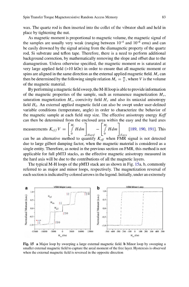
The typical M-H loops of the pMTJ stack are as shown in Fig. 15a, b, commonly
referred to as major and minor loops, respectively. The magnetization reversal of
each section is indicated by colored arrows in the legend. Initially, under an extremely
a
b
Fig. 15 a Major loop by sweeping a large external magnetic field. b Minor loop by sweeping a
smaller external magnetic field to capture the areal moment of the free layer. Hysteresis is observed
when the external magnetic field is reversed in the opposite direction
83
wax. The quartz rod is then inserted into the collet of the vibrator shaft and held in
place by tightening the nut.
As magnetic moment is proportional to magnetic volume, the magnetic signal of
the samples are usually very weak (ranging between 10
–4 and 10
–6 emu) and can
be easily drowned by the signal arising from the diamagnetic property of the quartz
rod, Si substrate and teflon tape. Therefore, there is a need to perform additional
background correction, by mathematically removing the slope and offset due to the
diamagnetism. Unless otherwise specified, the magnetic moment m is saturated at
very large applied field (>10 kOe) in order to ensure that all magnetic moment or
spins are aligned in the same direction as the external applied magnetic field. M s can
then be determined by the following simple relation M s =
m
V
, where V is the volume
of the magnetic material.
By performing a magnetic field sweep, the M-H loop is able to provide information
of the magnetic properties of the sample, such as remanence magnetization M r ,
saturation magnetization M s , coercivity field H c and also its uniaxial anisotropy
field H k . An external applied magnetic field can also be swept under user-defined
variable conditions (temperature, angle) in order to characterize the behavior of
the magnetic sample at each field step size. The effective anisotropy energy Keff
can then be determined from the enclosed area within the easy and the hard axes
measurements K e f f V =
M s
0
Hdm
Hard
−
M s
0
Hdm
Easy
[189, 190, 191]. This
can be an alternative method to quantify K eff when FMR signal is not detected
due to large gilbert damping factor, when the magnetic material is considered as a
single entity. Therefore, as noted in the previous section on FMR, this method is not
applicable for full pMTJ stacks, as the effective magnetic anisotropy measured in
the hard axis will be due to the contributions of all the magnetic layers.
The typical M-H loops of the pMTJ stack are as shown in Fig. 15a, b, commonly
referred to as major and minor loops, respectively. The magnetization reversal of
each section is indicated by colored arrows in the legend. Initially, under an extremely
a
b
Fig. 15 a Major loop by sweeping a large external magnetic field. b Minor loop by sweeping a
smaller external magnetic field to capture the areal moment of the free layer. Hysteresis is observed
when the external magnetic field is reversed in the opposite direction