

162
J. Lourembam and J. Huang
Fig. 8 a, b In precessional switching, a voltage is applied to bring the magnetization in-plane. This
then causes the magnetization to precess about the applied magnetic field in the x-direction. Half a
Larmor period causes the m Z to flip while a full period causes m Z to return to its original direction.
c Switching probability of MRAM in precessional switching. Shown here is anti-parallel to parallel
switching. The switching probability decreases with the higher-order periods. Different MTJs also
show random changes to the starting position or offset.
Fig. 9 a The switching probability contour plot showing precessional switching from AP to P,
b The switching probability from P to AP. For a certain number of precessional cycles, the Larmor
period (τ) shortens on increasing the amplitude of H x . This is shown by the ridges in the colormap
for both Fig. a and b. Reproduced from [24] © 2018, with the permission of AIP Publishing
J. Lourembam and J. Huang
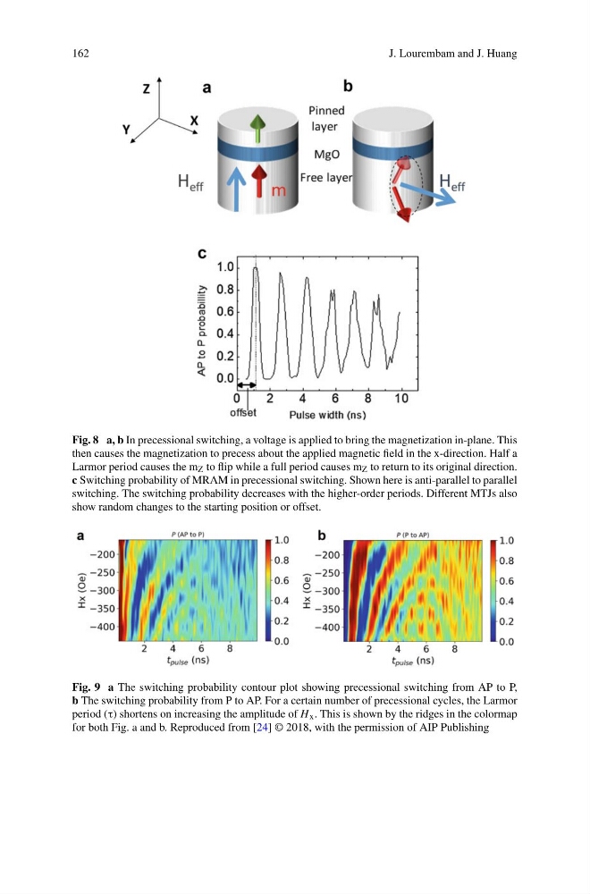
Fig. 8 a, b In precessional switching, a voltage is applied to bring the magnetization in-plane. This
then causes the magnetization to precess about the applied magnetic field in the x-direction. Half a
Larmor period causes the m Z to flip while a full period causes m Z to return to its original direction.
c Switching probability of MRAM in precessional switching. Shown here is anti-parallel to parallel
switching. The switching probability decreases with the higher-order periods. Different MTJs also
show random changes to the starting position or offset.
Fig. 9 a The switching probability contour plot showing precessional switching from AP to P,
b The switching probability from P to AP. For a certain number of precessional cycles, the Larmor
period (τ) shortens on increasing the amplitude of H x . This is shown by the ridges in the colormap
for both Fig. a and b. Reproduced from [24] © 2018, with the permission of AIP Publishing