

6
P. K. Muduli et al.
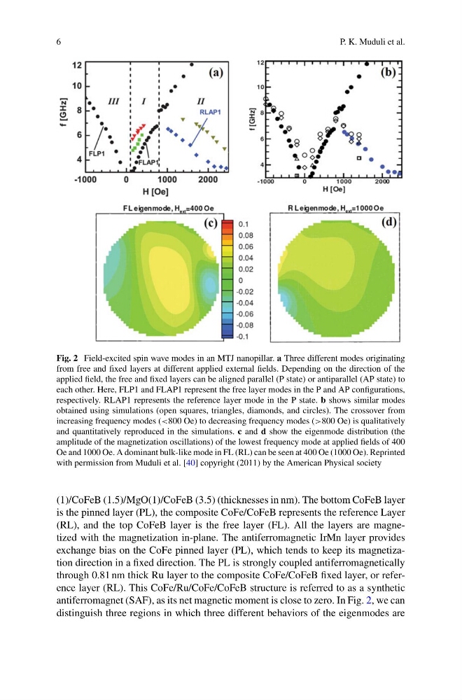
Fig. 2 Field-excited spin wave modes in an MTJ nanopillar. a Three different modes originating
from free and fixed layers at different applied external fields. Depending on the direction of the
applied field, the free and fixed layers can be aligned parallel (P state) or antiparallel (AP state) to
each other. Here, FLP1 and FLAP1 represent the free layer modes in the P and AP configurations,
respectively. RLAP1 represents the reference layer mode in the P state. b shows similar modes
obtained using simulations (open squares, triangles, diamonds, and circles). The crossover from
increasing frequency modes (<800 Oe) to decreasing frequency modes (>800 Oe) is qualitatively
and quantitatively reproduced in the simulations. c and d show the eigenmode distribution (the
amplitude of the magnetization oscillations) of the lowest frequency mode at applied fields of 400
Oe and 1000 Oe. A dominant bulk-like mode in FL (RL) can be seen at 400 Oe (1000 Oe). Reprinted
with permission from Muduli et al. [40] copyright (2011) by the American Physical society
(1)/CoFeB (1.5)/MgO(1)/CoFeB (3.5) (thicknesses in nm). The bottom CoFeB layer
is the pinned layer (PL), the composite CoFe/CoFeB represents the reference Layer
(RL), and the top CoFeB layer is the free layer (FL). All the layers are magnetized with the magnetization in-plane. The antiferromagnetic IrMn layer provides
exchange bias on the CoFe pinned layer (PL), which tends to keep its magnetization direction in a fixed direction. The PL is strongly coupled antiferromagnetically
through 0.81 nm thick Ru layer to the composite CoFe/CoFeB fixed layer, or reference layer (RL). This CoFe/Ru/CoFe/CoFeB structure is referred to as a synthetic
antiferromagnet (SAF), as its net magnetic moment is close to zero. In Fig. 2, we can
distinguish three regions in which three different behaviors of the eigenmodes are
P. K. Muduli et al.
Fig. 2 Field-excited spin wave modes in an MTJ nanopillar. a Three different modes originating
from free and fixed layers at different applied external fields. Depending on the direction of the
applied field, the free and fixed layers can be aligned parallel (P state) or antiparallel (AP state) to
each other. Here, FLP1 and FLAP1 represent the free layer modes in the P and AP configurations,
respectively. RLAP1 represents the reference layer mode in the P state. b shows similar modes
obtained using simulations (open squares, triangles, diamonds, and circles). The crossover from
increasing frequency modes (<800 Oe) to decreasing frequency modes (>800 Oe) is qualitatively
and quantitatively reproduced in the simulations. c and d show the eigenmode distribution (the
amplitude of the magnetization oscillations) of the lowest frequency mode at applied fields of 400
Oe and 1000 Oe. A dominant bulk-like mode in FL (RL) can be seen at 400 Oe (1000 Oe). Reprinted
with permission from Muduli et al. [40] copyright (2011) by the American Physical society
(1)/CoFeB (1.5)/MgO(1)/CoFeB (3.5) (thicknesses in nm). The bottom CoFeB layer
is the pinned layer (PL), the composite CoFe/CoFeB represents the reference Layer
(RL), and the top CoFeB layer is the free layer (FL). All the layers are magnetized with the magnetization in-plane. The antiferromagnetic IrMn layer provides
exchange bias on the CoFe pinned layer (PL), which tends to keep its magnetization direction in a fixed direction. The PL is strongly coupled antiferromagnetically
through 0.81 nm thick Ru layer to the composite CoFe/CoFeB fixed layer, or reference layer (RL). This CoFe/Ru/CoFe/CoFeB structure is referred to as a synthetic
antiferromagnet (SAF), as its net magnetic moment is close to zero. In Fig. 2, we can
distinguish three regions in which three different behaviors of the eigenmodes are