

3.4 Solved Problems
63
node 5:
E I Y
X 2 (u 6 − 2u 5 + u 4 ) =
F 0 L
6
,
(3.116)
node 6:
E I Y
X 2 (u 7 − 2u 6 + u 5 ) =
F 0 L
12
.
(3.117)
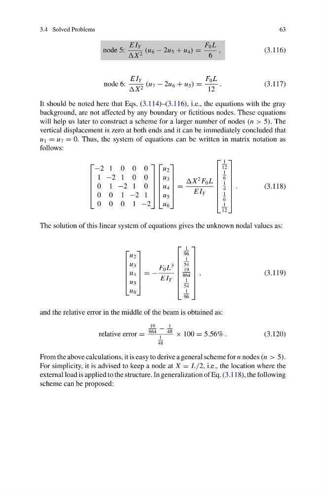
It should be noted here that Eqs. (3.114)–(3.116), i.e., the equations with the gray
background, are not affected by any boundary or fictitious nodes. These equations
will help us later to construct a scheme for a larger number of nodes (n > 5). The
vertical displacement is zero at both ends and it can be immediately concluded that
u 1 = u 7 = 0. Thus, the system of equations can be written in matrix notation as
follows:
⎡
⎢
⎢
⎢
⎢
⎣
−2 1 0 0 0
1 −2 1 0 0
0 1 −2 1 0
0 0 1 −2 1
0 0 0 1 −2
⎤
⎥
⎥
⎥
⎥
⎦
⎡
⎢
⎢
⎢
⎢
⎣
u 2
u 3
u 4
u 5
u 6
⎤
⎥
⎥
⎥
⎥
⎦
=
X
2 F 0 L
E I Y
⎡
⎢
⎢
⎢
⎢
⎢
⎢
⎣
1
12
1
6
1
4
1
6
1
12
⎤
⎥
⎥
⎥
⎥
⎥
⎥
⎦
.
(3.118)
The solution of this linear system of equations gives the unknown nodal values as:
⎡
⎢
⎢
⎢
⎢
⎣
u 2
u 3
u 4
u 5
u 6
⎤
⎥
⎥
⎥
⎥
⎦
= −
F 0 L
3
E I Y
⎡
⎢
⎢
⎢
⎢
⎢
⎢
⎣
1
96
1
54
19
864
1
54
1
96
⎤
⎥
⎥
⎥
⎥
⎥
⎥
⎦
,
(3.119)
and the relative error in the middle of the beam is obtained as:
relative error =
19
864
−
1
48
1
48
× 100 = 5.56% .
(3.120)
From the above calculations, it is easy to derive a general scheme for n nodes (n > 5).
For simplicity, it is advised to keep a node at X = L/2, i.e., the location where the
external load is applied to the structure. In generalization of Eq. (3.118), the following
scheme can be proposed:
63
node 5:
E I Y
X 2 (u 6 − 2u 5 + u 4 ) =
F 0 L
6
,
(3.116)
node 6:
E I Y
X 2 (u 7 − 2u 6 + u 5 ) =
F 0 L
12
.
(3.117)
It should be noted here that Eqs. (3.114)–(3.116), i.e., the equations with the gray
background, are not affected by any boundary or fictitious nodes. These equations
will help us later to construct a scheme for a larger number of nodes (n > 5). The
vertical displacement is zero at both ends and it can be immediately concluded that
u 1 = u 7 = 0. Thus, the system of equations can be written in matrix notation as
follows:
⎡
⎢
⎢
⎢
⎢
⎣
−2 1 0 0 0
1 −2 1 0 0
0 1 −2 1 0
0 0 1 −2 1
0 0 0 1 −2
⎤
⎥
⎥
⎥
⎥
⎦
⎡
⎢
⎢
⎢
⎢
⎣
u 2
u 3
u 4
u 5
u 6
⎤
⎥
⎥
⎥
⎥
⎦
=
X
2 F 0 L
E I Y
⎡
⎢
⎢
⎢
⎢
⎢
⎢
⎣
1
12
1
6
1
4
1
6
1
12
⎤
⎥
⎥
⎥
⎥
⎥
⎥
⎦
.
(3.118)
The solution of this linear system of equations gives the unknown nodal values as:
⎡
⎢
⎢
⎢
⎢
⎣
u 2
u 3
u 4
u 5
u 6
⎤
⎥
⎥
⎥
⎥
⎦
= −
F 0 L
3
E I Y
⎡
⎢
⎢
⎢
⎢
⎢
⎢
⎣
1
96
1
54
19
864
1
54
1
96
⎤
⎥
⎥
⎥
⎥
⎥
⎥
⎦
,
(3.119)
and the relative error in the middle of the beam is obtained as:
relative error =
19
864
−
1
48
1
48
× 100 = 5.56% .
(3.120)
From the above calculations, it is easy to derive a general scheme for n nodes (n > 5).
For simplicity, it is advised to keep a node at X = L/2, i.e., the location where the
external load is applied to the structure. In generalization of Eq. (3.118), the following
scheme can be proposed: