

3.1 The Basics of an Euler–Bernoulli Beam
39
Table 3.1 Different formulations of the basic equations for a Bernoulli beam (bending occurs in
the X -Z plane), with L 2 (. . . ) =
d 2 (... )
dX 2
Specific formulation
General formulation [1]
Kinematics
ε X (X, Z ) = −Z
d 2 u Z (X )
dX 2
ε X (X, Z ) = −Z L 2 (u Z (X ))
κ = −
d 2 u Z (X )
dX 2
κ = −L 2 (u Z (X ))
Constitution
σ X (X, Z ) = Eε X (X, Z )
σ X (X, Z ) = Cε X (X, Z )
M Y (X ) = E I Y κ(X )
M Y (X ) = Dκ(X )
Equilibrium
Force
dQ Z (X )
dX
= −q Z (X )
Moment
dM Y (X )
dX
= Q Z (X )
Combined
d 2 M Y (X )
dX 2
+ q Z (X ) = 0
L T
2 (M Y (X )) + q Z (X ) = 0
PDE
d 2
dX 2
E I Y
d 2 u Z (X )
dX 2
− q Z (X ) = 0
L T
2 (DL 2 (u Z (X ))) − q Z (X ) = 0
d
dX
E I Y
d 2 u Z (X )
dX 2
= −Q Z (X )
E I Y
d 2 u Z (X )
dX 2
= −M Y (X )
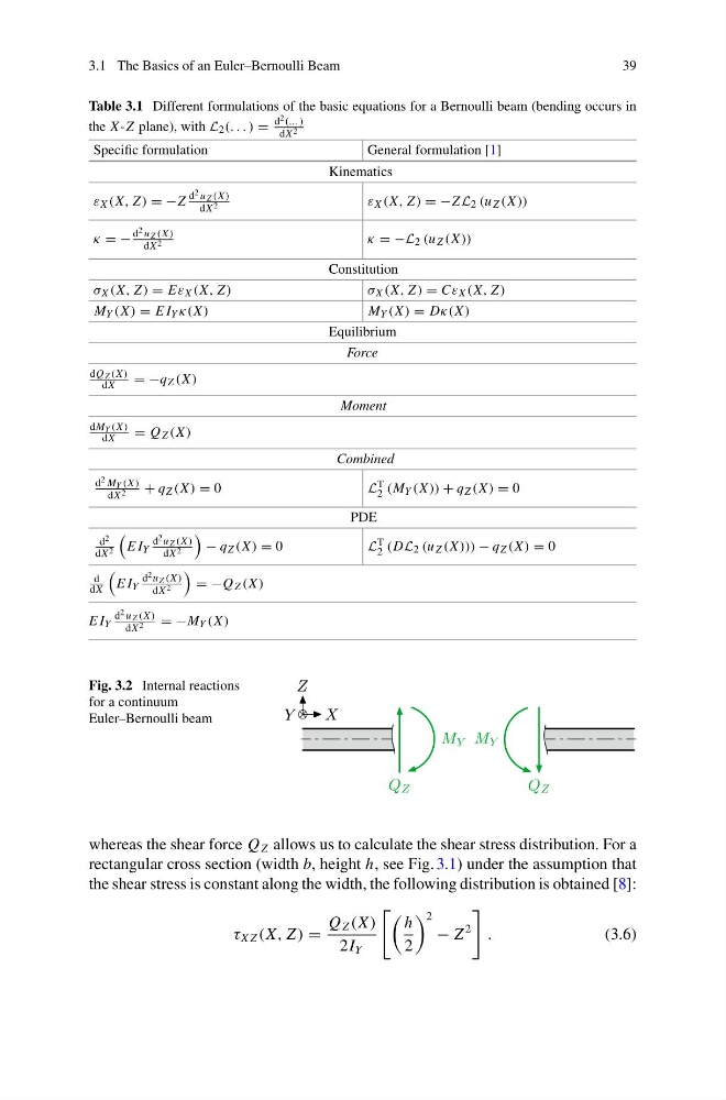
Fig. 3.2 Internal reactions
for a continuum
Euler–Bernoulli beam
whereas the shear force Q Z allows us to calculate the shear stress distribution. For a
rectangular cross section (width b, height h, see Fig. 3.1) under the assumption that
the shear stress is constant along the width, the following distribution is obtained [8]:
τ X Z (X, Z ) =
Q Z (X )
2I Y
h
2
2
− Z
2
.
(3.6)
39
Table 3.1 Different formulations of the basic equations for a Bernoulli beam (bending occurs in
the X -Z plane), with L 2 (. . . ) =
d 2 (... )
dX 2
Specific formulation
General formulation [1]
Kinematics
ε X (X, Z ) = −Z
d 2 u Z (X )
dX 2
ε X (X, Z ) = −Z L 2 (u Z (X ))
κ = −
d 2 u Z (X )
dX 2
κ = −L 2 (u Z (X ))
Constitution
σ X (X, Z ) = Eε X (X, Z )
σ X (X, Z ) = Cε X (X, Z )
M Y (X ) = E I Y κ(X )
M Y (X ) = Dκ(X )
Equilibrium
Force
dQ Z (X )
dX
= −q Z (X )
Moment
dM Y (X )
dX
= Q Z (X )
Combined
d 2 M Y (X )
dX 2
+ q Z (X ) = 0
L T
2 (M Y (X )) + q Z (X ) = 0
PDE
d 2
dX 2
E I Y
d 2 u Z (X )
dX 2
− q Z (X ) = 0
L T
2 (DL 2 (u Z (X ))) − q Z (X ) = 0
d
dX
E I Y
d 2 u Z (X )
dX 2
= −Q Z (X )
E I Y
d 2 u Z (X )
dX 2
= −M Y (X )
Fig. 3.2 Internal reactions
for a continuum
Euler–Bernoulli beam
whereas the shear force Q Z allows us to calculate the shear stress distribution. For a
rectangular cross section (width b, height h, see Fig. 3.1) under the assumption that
the shear stress is constant along the width, the following distribution is obtained [8]:
τ X Z (X, Z ) =
Q Z (X )
2I Y
h
2
2
− Z
2
.
(3.6)