

5.1 Basics of the Layered Approach
105
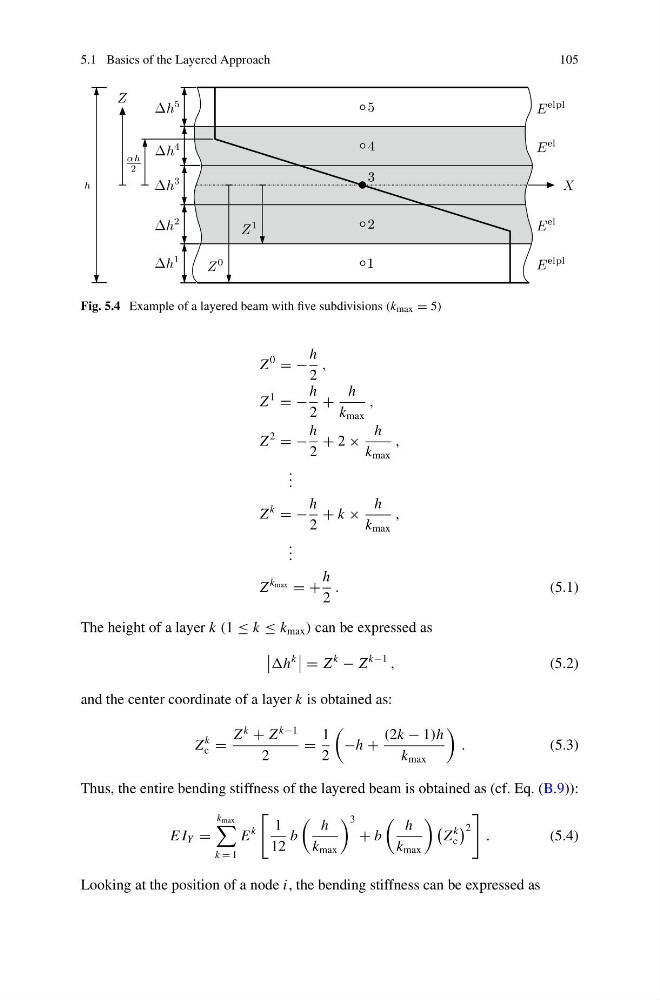
Fig. 5.4 Example of a layered beam with five subdivisions (k max = 5)
Z
0
= −
h
2
,
Z
1
= −
h
2
+
h
k max
,
Z
2
= −
h
2
+ 2 ×
h
k max
,
. . .
Z
k
= −
h
2
+ k ×
h
k max
,
. . .
Z
k max = +
h
2
.
(5.1)
The height of a layer k (1 ≤ k ≤ k max ) can be expressed as
k
= Z
k
− Z
k−1
,
(5.2)
and the center coordinate of a layer k is obtained as:
Z
k
c =
Z
k
+ Z
k−1
2
=
1
2
−h +
(2k − 1)h
k max
.
(5.3)
Thus, the entire bending stiffness of the layered beam is obtained as (cf. Eq. (B.9)):
E I Y =
k max
k = 1
E
k
1
12
b
h
k max
3
+ b
h
k max
Z
k
c
2
.
(5.4)
Looking at the position of a node i, the bending stiffness can be expressed as
105
Fig. 5.4 Example of a layered beam with five subdivisions (k max = 5)
Z
0
= −
h
2
,
Z
1
= −
h
2
+
h
k max
,
Z
2
= −
h
2
+ 2 ×
h
k max
,
. . .
Z
k
= −
h
2
+ k ×
h
k max
,
. . .
Z
k max = +
h
2
.
(5.1)
The height of a layer k (1 ≤ k ≤ k max ) can be expressed as
k
= Z
k
− Z
k−1
,
(5.2)
and the center coordinate of a layer k is obtained as:
Z
k
c =
Z
k
+ Z
k−1
2
=
1
2
−h +
(2k − 1)h
k max
.
(5.3)
Thus, the entire bending stiffness of the layered beam is obtained as (cf. Eq. (B.9)):
E I Y =
k max
k = 1
E
k
1
12
b
h
k max
3
+ b
h
k max
Z
k
c
2
.
(5.4)
Looking at the position of a node i, the bending stiffness can be expressed as