

92
4 Investigation of Timoshenko Beams in the Elastic Range
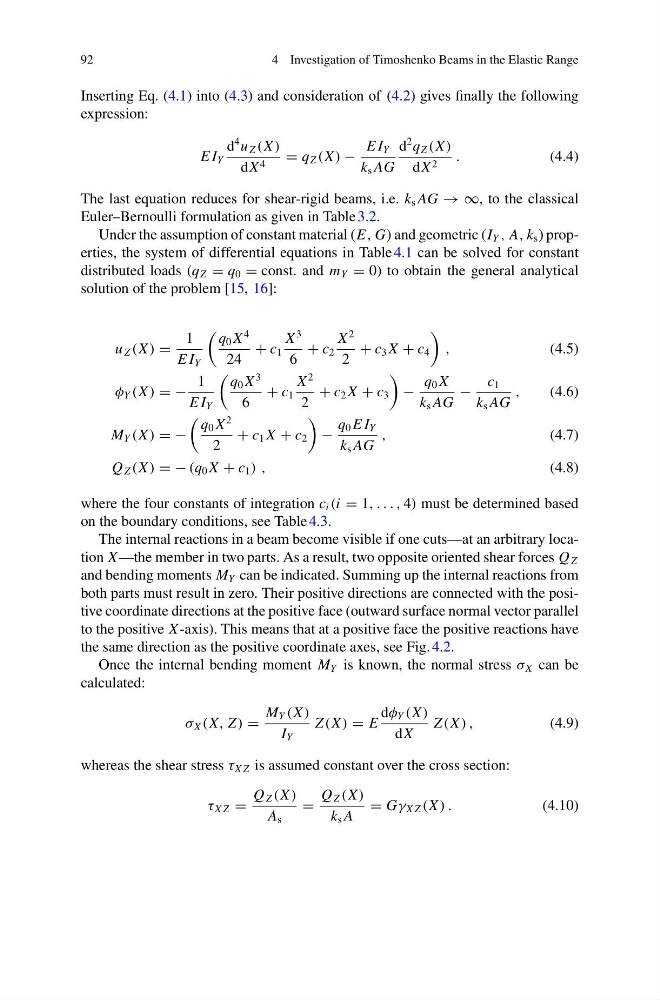
Inserting Eq. (4.1) into (4.3) and consideration of (4.2) gives finally the following
expression:
E I Y
d
4 u Z (X )
dX 4 = q Z (X ) −
E I Y
k s AG
d
2 q Z (X )
dX 2 .
(4.4)
The last equation reduces for shear-rigid beams, i.e. k s AG → ∞, to the classical
Euler–Bernoulli formulation as given in Table 3.2.
Under the assumption of constant material (E, G) and geometric (I Y , A, k s ) properties, the system of differential equations in Table 4.1 can be solved for constant
distributed loads (q Z = q 0 = const. and m Y = 0) to obtain the general analytical
solution of the problem [15, 16]:
u Z (X ) =
1
E I Y
q 0 X
4
24
+ c 1
X
3
6
+ c 2
X
2
2
+ c 3 X + c 4
,
(4.5)
φ Y (X ) = −
1
E I Y
q 0 X
3
6
+ c 1
X
2
2
+ c 2 X + c 3
−
q 0 X
k s AG
−
c 1
k s AG
,
(4.6)
M Y (X ) = −
q 0 X
2
2
+ c 1 X + c 2
−
q 0 E I Y
k s AG
,
(4.7)
Q Z (X ) = − (q 0 X + c 1 ) ,
(4.8)
where the four constants of integration c i (i = 1, . . . , 4) must be determined based
on the boundary conditions, see Table 4.3.
The internal reactions in a beam become visible if one cuts—at an arbitrary location X —the member in two parts. As a result, two opposite oriented shear forces Q Z
and bending moments M Y can be indicated. Summing up the internal reactions from
both parts must result in zero. Their positive directions are connected with the positive coordinate directions at the positive face (outward surface normal vector parallel
to the positive X -axis). This means that at a positive face the positive reactions have
the same direction as the positive coordinate axes, see Fig. 4.2.
Once the internal bending moment M Y is known, the normal stress σ X can be
calculated:
σ X (X, Z ) =
M Y (X )
I Y
Z (X ) = E
dφ Y (X )
dX
Z (X ) ,
(4.9)
whereas the shear stress τ X Z is assumed constant over the cross section:
τ X Z =
Q Z (X )
A s
=
Q Z (X )
k s A
= Gγ X Z (X ) .
(4.10)
4 Investigation of Timoshenko Beams in the Elastic Range
Inserting Eq. (4.1) into (4.3) and consideration of (4.2) gives finally the following
expression:
E I Y
d
4 u Z (X )
dX 4 = q Z (X ) −
E I Y
k s AG
d
2 q Z (X )
dX 2 .
(4.4)
The last equation reduces for shear-rigid beams, i.e. k s AG → ∞, to the classical
Euler–Bernoulli formulation as given in Table 3.2.
Under the assumption of constant material (E, G) and geometric (I Y , A, k s ) properties, the system of differential equations in Table 4.1 can be solved for constant
distributed loads (q Z = q 0 = const. and m Y = 0) to obtain the general analytical
solution of the problem [15, 16]:
u Z (X ) =
1
E I Y
q 0 X
4
24
+ c 1
X
3
6
+ c 2
X
2
2
+ c 3 X + c 4
,
(4.5)
φ Y (X ) = −
1
E I Y
q 0 X
3
6
+ c 1
X
2
2
+ c 2 X + c 3
−
q 0 X
k s AG
−
c 1
k s AG
,
(4.6)
M Y (X ) = −
q 0 X
2
2
+ c 1 X + c 2
−
q 0 E I Y
k s AG
,
(4.7)
Q Z (X ) = − (q 0 X + c 1 ) ,
(4.8)
where the four constants of integration c i (i = 1, . . . , 4) must be determined based
on the boundary conditions, see Table 4.3.
The internal reactions in a beam become visible if one cuts—at an arbitrary location X —the member in two parts. As a result, two opposite oriented shear forces Q Z
and bending moments M Y can be indicated. Summing up the internal reactions from
both parts must result in zero. Their positive directions are connected with the positive coordinate directions at the positive face (outward surface normal vector parallel
to the positive X -axis). This means that at a positive face the positive reactions have
the same direction as the positive coordinate axes, see Fig. 4.2.
Once the internal bending moment M Y is known, the normal stress σ X can be
calculated:
σ X (X, Z ) =
M Y (X )
I Y
Z (X ) = E
dφ Y (X )
dX
Z (X ) ,
(4.9)
whereas the shear stress τ X Z is assumed constant over the cross section:
τ X Z =
Q Z (X )
A s
=
Q Z (X )
k s A
= Gγ X Z (X ) .
(4.10)