

Kabir, Kantola, and Llorente Santos
208
Policy Negotiation
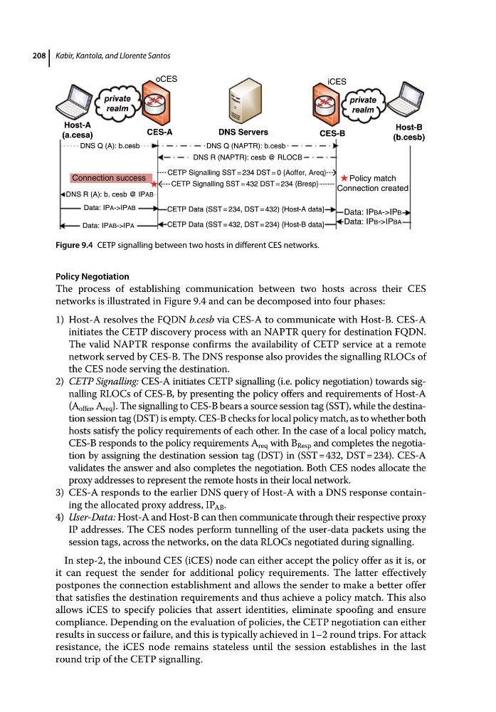
The process of establishing communication between two hosts across their CES
networks is illustrated in Figure 9.4 and can be decomposed into four phases:
1) Host‐A resolves the FQDN b.cesb via CES‐A to communicate with Host‐B. CES‐A
initiates the CETP discovery process with an NAPTR query for destination FQDN.
The valid NAPTR response confirms the availability of CETP service at a remote
network served by CES‐B. The DNS response also provides the signalling RLOCs of
the CES node serving the destination.
2) CETP Signalling: CES‐A initiates CETP signalling (i.e. policy negotiation) towards sig‑
nalling RLOCs of CES‐B, by presenting the policy offers and requirements of Host‐A
(A offer , A req }. The signalling to CES‐B bears a source session tag (SST), while the destina‑
tion session tag (DST) is empty. CES‐B checks for local policy match, as to whether both
hosts satisfy the policy requirements of each other. In the case of a local policy match,
CES‐B responds to the policy requirements A req with B Resp and completes the negotia‑
tion by assigning the destination session tag (DST) in (SST = 432, DST = 234). CES‐A
validates the answer and also completes the negotiation. Both CES nodes allocate the
proxy addresses to represent the remote hosts in their local network.
3) CES‐A responds to the earlier DNS query of Host‐A with a DNS response contain‑
ing the allocated proxy address, IP AB .
4) User‐Data: Host‐A and Host‐B can then communicate through their respective proxy
IP addresses. The CES nodes perform tunnelling of the user‐data packets using the
session tags, across the networks, on the data RLOCs negotiated during signalling.
In step‐2, the inbound CES (iCES) node can either accept the policy offer as it is, or
it can request the sender for additional policy requirements. The latter effectively
postpones the connection establishment and allows the sender to make a better offer
that satisfies the destination requirements and thus achieve a policy match. This also
allows iCES to specify policies that assert identities, eliminate spoofing and ensure
compliance. Depending on the evaluation of policies, the CETP negotiation can either
results in success or failure, and this is typically achieved in 1–2 round trips. For attack
resistance, the iCES node remains stateless until the session establishes in the last
round trip of the CETP signalling.
Host-A
(a.cesa)
Host-B
(b.cesb)
CES-A
private
realm
private
realm
CES-B
DNS Servers
oCES
DNS Q (A): b.cesb
Connection success
Policy match
Connection created
Data: IPBA->IPB
Data: IPB->IPBA
DNS R (A): b. cesb @ IPAB
Data: IPA->IPAB
Data: IPAB->IPA
CETP Signalling SST = 432 DST = 234 {Bresp}
DNS Q (NAPTR): b.cesb
DNS R (NAPTR): cesb @ RLOCB
iCES
CETP Data (SST = 432, DST = 234) {Host-B data}
CETP Data (SST = 234, DST = 432) {Host-A data}
CETP Signalling SST = 234 DST = 0 {Aoffer, Areq}
Figure 9.4 CETP signalling between two hosts in different CES networks.
208
Policy Negotiation
The process of establishing communication between two hosts across their CES
networks is illustrated in Figure 9.4 and can be decomposed into four phases:
1) Host‐A resolves the FQDN b.cesb via CES‐A to communicate with Host‐B. CES‐A
initiates the CETP discovery process with an NAPTR query for destination FQDN.
The valid NAPTR response confirms the availability of CETP service at a remote
network served by CES‐B. The DNS response also provides the signalling RLOCs of
the CES node serving the destination.
2) CETP Signalling: CES‐A initiates CETP signalling (i.e. policy negotiation) towards sig‑
nalling RLOCs of CES‐B, by presenting the policy offers and requirements of Host‐A
(A offer , A req }. The signalling to CES‐B bears a source session tag (SST), while the destina‑
tion session tag (DST) is empty. CES‐B checks for local policy match, as to whether both
hosts satisfy the policy requirements of each other. In the case of a local policy match,
CES‐B responds to the policy requirements A req with B Resp and completes the negotia‑
tion by assigning the destination session tag (DST) in (SST = 432, DST = 234). CES‐A
validates the answer and also completes the negotiation. Both CES nodes allocate the
proxy addresses to represent the remote hosts in their local network.
3) CES‐A responds to the earlier DNS query of Host‐A with a DNS response contain‑
ing the allocated proxy address, IP AB .
4) User‐Data: Host‐A and Host‐B can then communicate through their respective proxy
IP addresses. The CES nodes perform tunnelling of the user‐data packets using the
session tags, across the networks, on the data RLOCs negotiated during signalling.
In step‐2, the inbound CES (iCES) node can either accept the policy offer as it is, or
it can request the sender for additional policy requirements. The latter effectively
postpones the connection establishment and allows the sender to make a better offer
that satisfies the destination requirements and thus achieve a policy match. This also
allows iCES to specify policies that assert identities, eliminate spoofing and ensure
compliance. Depending on the evaluation of policies, the CETP negotiation can either
results in success or failure, and this is typically achieved in 1–2 round trips. For attack
resistance, the iCES node remains stateless until the session establishes in the last
round trip of the CETP signalling.
Host-A
(a.cesa)
Host-B
(b.cesb)
CES-A
private
realm
private
realm
CES-B
DNS Servers
oCES
DNS Q (A): b.cesb
Connection success
Policy match
Connection created
Data: IPBA->IPB
Data: IPB->IPBA
DNS R (A): b. cesb @ IPAB
Data: IPA->IPAB
Data: IPAB->IPA
CETP Signalling SST = 432 DST = 234 {Bresp}
DNS Q (NAPTR): b.cesb
DNS R (NAPTR): cesb @ RLOCB
iCES
CETP Data (SST = 432, DST = 234) {Host-B data}
CETP Data (SST = 234, DST = 432) {Host-A data}
CETP Signalling SST = 234 DST = 0 {Aoffer, Areq}
Figure 9.4 CETP signalling between two hosts in different CES networks.